SwissMX Endstation
The SwissMX (Serial WIth Solid-Support MX) is a fixed-target SFX endstation designed for high-throughput SFX and SFX pump-probe measurements. The endstation is composed of two pieces of instrumentation: the sample chamber and TELL sample changer. Together these enable the rapid rastering of large area fixed-targets and their prompt exchange using an adapted TELL robot system. The SwissMX can currently support two varieties of fixed-target: the PSI MISP (MIcro-Structured Polymer) chip and the Max Plank Institut (MPI) SOS (Sheet-On-Sheet) chip (Doak et al., 2018), although other targets such as the Oxford (Horrell et al., 2021) and HARE chips (Mehrabi et al., 2020) will be supported soon (2024).
Fixed-target data-collection
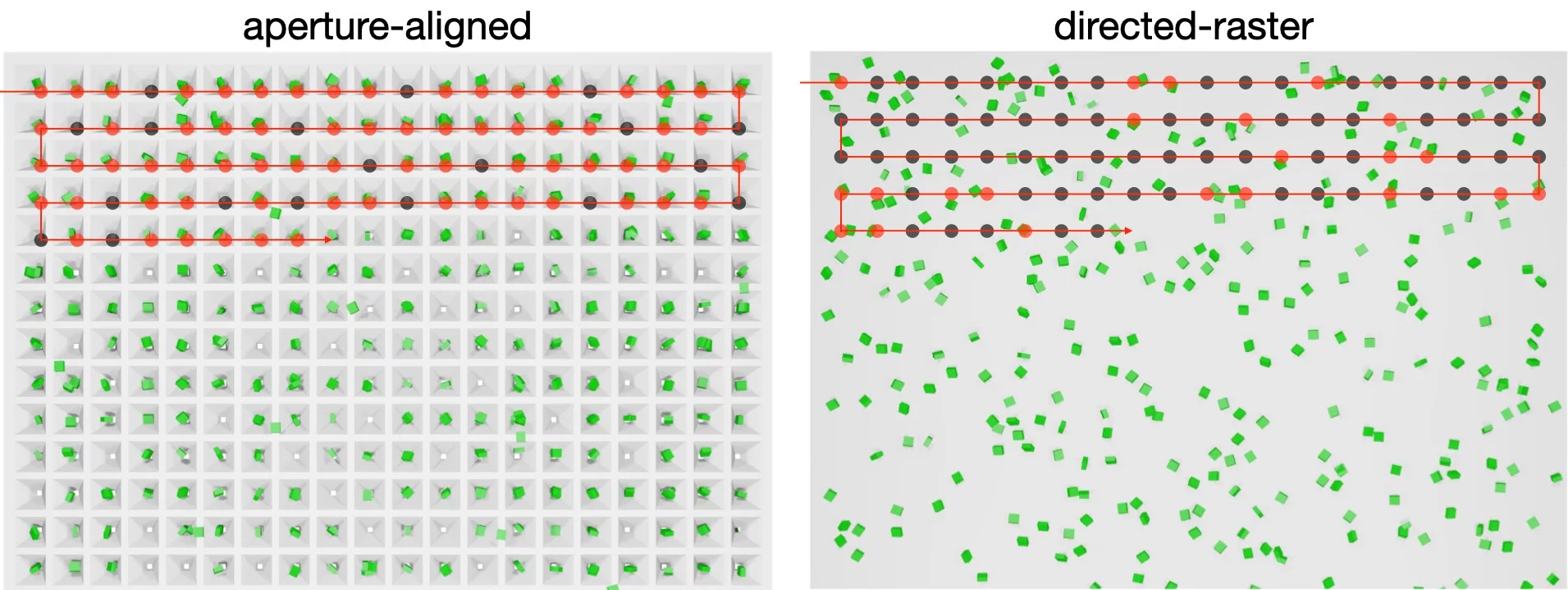
Fixed-targets can enable two types of data-collection: aperture-aligned, where crystals are loaded into precisely positioned cavities at known locations and sequentially exposed, or, directed-raster, where a raster grid is defined over crystals in completely random locations.
PSI MISP chips
The MIcro-Structure Polymer (MISP) fixed-targets were developed for the SwissMX endstation through a collaboration between the Laboratory for Macromolecules and Bioimaging (LSB) and the Laboratory for X-ray Nanoscience and Technologies (LXN) in the Photon Science Division (PSD) and the Laboratory of Nanoscale Biology (LNB) in the Division of Biology and Chemistry (BIO) at PSI. The chips are an attempt to combine the precision of silicon micro-fabrication technologies with a low-cost polymer materials. Like the Oxford and HARE chips, the MISP-chips are composed of a precise array of apertures. Protein crystals are loaded into these apertures by pipetting a micro-crystal solution to the surface and applying a vacuum or blotting away the excess solution from the underside. Once the the majority of the solution is removed, the chip is sealed between two pieces of film in a holder. Once loaded on the beamline, the apertures are rapidly rastered through in step with the XFEL pulse (this video from Diamond Light Source gives a nice overview of the process).

The left hand image shows the larger format MISP chip (23.0 mm fiducial spacing). The red, green and blue boxes show zoomed in versions of the corner fiducial markers, the central apertures and the chip labelling, respectively. The aperture spacing, or pitch, is currently set to 120 µm. The cavity and aperture size is typically 100 and 4-5 µm, respectively, although this is not uniform across the entire chips area with the 1-4 outer rows and columns of apertures exhibiting larger aperture sizes (>10 µm).
The MISP-chips are currently fabricated in two sizes and from two materials (transparent COC and opaque COP). The sizes are defined by the fiducial spacing and are currently: 12.5 and 23.0 mm. The opaque COP chips are necessary for laser pump-probe experiments to ensure that the pump light is transmitted through the chips and contaminates adjacent cavities. The opaque COP chips, due to the opaque film fabrication, have slightly different cavity properties. The table below gives a summary of these.
| transparent | opaque | ||
| material | COC | COP | |
| measurement type | SFX | SFX pump-probe | |
| fiducial width (µm) | 12.5 | 23.0 | 23.0 |
| pitch (µm) | 120.0 | ||
| cavity size (µm) | 100.0 | ||
| mean aperture size (µm) | 6.3 ± 1.0* | 8 ± 3.0† | |
| minimum crystal size (µm) | > 5.0 | > 10.0 | |
(*) Lysozyme crystals with a longest dimension as small as 4 µm have been caught in the chip apertures.
(†) It is very challenging to load single crystals into single wells as the crystal size decreases. An ideal crystal size for pump-probe in these chips is currently approximately 15-30 µm. Outside of these limits, the likelihood of crystal pump excitation decreases as either the number of crystals in the cavity increases or the crystal size limits the excited fraction. This is not to say it is impossible, but certainly not ideal.
MPI SOS fixed-targets
The SOS support was developed by the MPI as a cheap and highly effective way of mounting samples for serial crystallography measurements utilising a directed-raster style of data collection (Doak et al., 2018). These supports are a much more refined version of the thin-film sandwiches initially developed for use at the synchrotron (Huang et al., 2015, Axford et al., 2016). The key advance, other than the holder design, was the loading technique to ensure a minimal and uniform sample thickness across the thin-film sandwich over a large area.
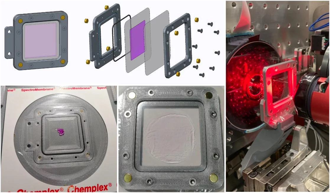
The top left-hand image is a schematic of the construction of the SOS chip. The bottom left-hand images show how a 10 µL volume of a viscous sample (in this case bacteriorhodopsin micro-crystals in LCP) is placed on the loader and sandwiched into the SOS chip holder. All left hand images were taken from (Doak et al., 2018). The right-hand image shows a SOS chip mounted on the SwissMX fast stages.
Recent commissioning has shown that a 25 x 25 µm grid (collected at 12 keV) yields undamaged data. The SOS supports with this spacing allow for a significant quality of data to be collected from a small area (250,000 images from 12.5 x 12.5 mm2); maximising the amount of data collected from the minimal amount of sample (8 µL). Smaller spacing may be possible but have yet to be tested.
The ideal samples for the SOS chips are either crystals grown in the Lipidic Cubic Phase (LCP) or concentrated solutions of micro-crystals that have been mixed with 2-5 % (w/v) ethyl cellulose making them moderately viscous. Crystals loaded simply in solution are liable to migrate as the chip is mounted due to gravity. Otherwise, the SOS supports are incredibly versatile, happily accepting both very small (≥1 µm) and large (>50 µm) crystal samples. Given this, and the small volumes required, the SOS chips are an ideal support for SFX measurements. SFX pump-probe using the SOS fixed-targets is currently the subject of commissioning but currently not advised.
Pump-probe measurements
Laser coupling
The SwissMX can be fibre coupled to EKSPLA nanosecond OPO located in the laser hutch (see Pump-laser at Cristallina-MX). The fibre coupling limits the usable laser energy achievable from the fibre to 5-10 µJ as Raman shifts have been observed at higher pulse energies; although, this is wavelength dependent. From the fibre, the laser is coupled to the sample position via the objective of the SwissMX on-axis viewing (OAV) system; co-aligning the X-ray and pump laser pulses.
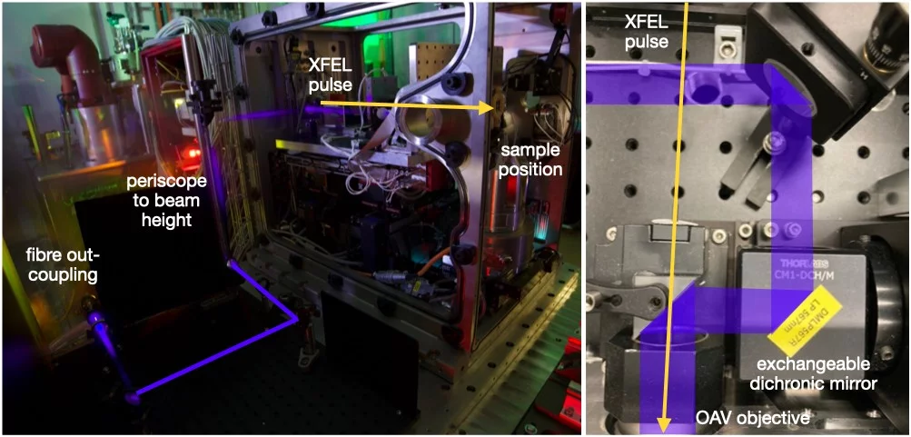
An overview of the SwissMX through-space laser path from the fibre out-coupling to the sample position. The left-hand image is a slightly-doctored, long exposure of the SwissMX showing the coupling of 450 nm light and using cold N2 gas to scatter the light. After the fibre out-coupling the light is collimated and directed via a periscope to the beam height and sample position. The right-hand image shows a top view of how the light is brought in-line to the XFEL pulse via a dichroic mirror. The OAV objective has a 0.5 mm hole through its centre for the transmission of the XFEL pulse.
Fixed-targets
The opaque MISP-chips are the only fixed-targets currently suitable for SFX pump-probe measurements using the SwissMX. The image below shows a comparison between the transparent and opaque chips. As can be seen, the light is highly transmitted through the transparent chips. Commissioning SFX pump-probe experiments confirm that the cavity-to-cavity light contamination using the transparent chips is extensive whereas the opaque chips remove this problem.
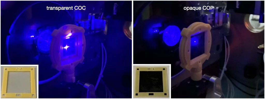
A comparison of the observable laser scatter from the transparent (left) and opaque (right) MISP chips.
Available time delays
Long time delays (>0.5 ms) for SFX pump-probe measurements will be possible using the SwissMX in near future. However, due to the current stage of development of the stages and control software, only time-delays from 50 ns to 0.5 ms have been fully commissioned for 2024-I. The implementation of long time delays is an absolute priority during 2024.
Summary pump-probe parameters
| pulse-width (FWHM) | 3.2 ns at 450 nm |
| maximum pulse energy | 2 µJ |
| commissioned wavelengths | 410 - 700 nm |
| beam size | 30 x 30 µm2 at 450 nm |
| ΔT range | 50 ns - 0.5 ms |
| fixed-targets | opaque MISP-chips |
TELL sample changer
To increase the throughput of the SwissMX, a TELL robot system has been adapted to work with the large area fixed-targets and a humidified storage container. The relative humidity of the chamber is set to 80 %, a level found to be sufficient for maintaining the diffraction potential and number of crystals in a fixed-target for a series of test proteins [lysozyme, thaumatin, bacteriorhodopsin in LCP and insulin (Huang et al., 2022)] for up to seven days. The survival of a variety of protein crystals during commissioning using the humidified storage system appears to have born out these initial findings. The system simplifies and speeds up the process of sample exchange as the continual opening and searching of the hutch is dramatically minimised when the TELL can be employed. Sample preparation is also improved as 10-20 MISP chips can be prepared at once and safely stored until data-collection.
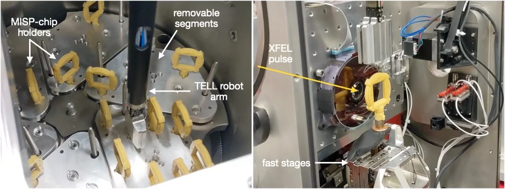
The left-hand image shows a view inside the humidified storage container as the TELL robot is removing a MISP-chip sample to load at the sample position. The base of the dewar is composed of six removable segments that can each hold nine samples each, giving a total storage capacity of 54 fixed-targets. The right-hand image shows the MISP chip holder as it is mounted on the fast-stages at the sample position.
The use of the TELL robot is currently only possible using the MISP chips. The SOS chips use a different fixation method to the fast-stages making them incompatible with the robot. However, since SOS chip data-collections are typically long (250,000 images at 100 Hz = 41.7 min) compared to a 23.0 mm MISP chip (26,000 images at 100 Hz = 4.3 min ), the need for rapid sample exchange of the SOS chip is reduced.