Hardware
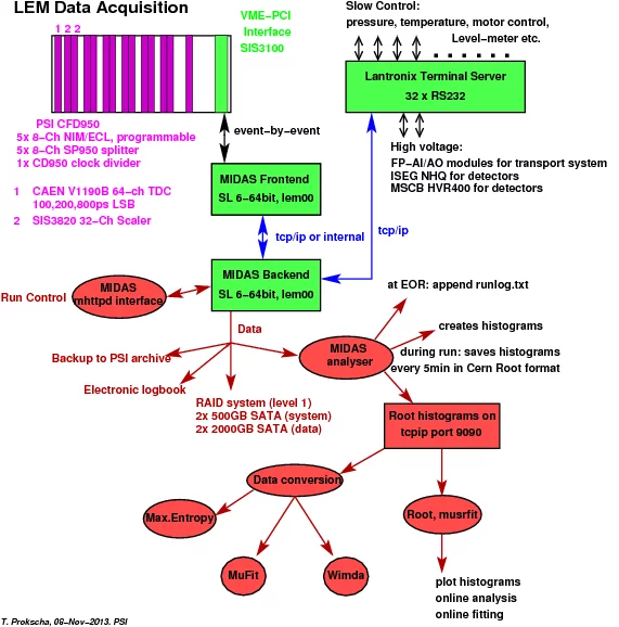
Since september 2005 the LEM frontend hardware consists of standard NIM modules and a VME crate with programmable constant fraction discriminators (PSI CFD950), a multihit TDC (CAEN V1190) for digitizing of time information, and a scaler module (SIS3820) for rate measurements.
The VME frontend process for readout of the VME TDC data is running on the backend server and connected to the VME crate by a SIS 3100/1100 VME-PCI interface. The backend computer consists of a Scientific Linux 4 server Intel SR2400 (Thomas-Krenn.AG) with 2 Xeon CPU's, a RAID-1 system, backup fan kit and 2 hot-swap power supplies. Presently, all front- and backend processes are running on one server; in future, the VME readout could be performed by a SHARC processor that is an option of the SIS3100 VME card. The complete event evaluation is done in software: the TDC is operated in Continuous Storage Mode, and the frontend process reads all the TDC data, searches for events that fulfill the trigger condition, and builds the events to be sent to the DAQ system.
The VME frontend process for readout of the VME TDC data is running on the backend server and connected to the VME crate by a SIS 3100/1100 VME-PCI interface. The backend computer consists of a Scientific Linux 4 server Intel SR2400 (Thomas-Krenn.AG) with 2 Xeon CPU's, a RAID-1 system, backup fan kit and 2 hot-swap power supplies. Presently, all front- and backend processes are running on one server; in future, the VME readout could be performed by a SHARC processor that is an option of the SIS3100 VME card. The complete event evaluation is done in software: the TDC is operated in Continuous Storage Mode, and the frontend process reads all the TDC data, searches for events that fulfill the trigger condition, and builds the events to be sent to the DAQ system.
The LEM slow control parameters like pressure, temperature, level-meter, high-voltages etc. are read and managed through a Lantronix ETS32PR 32-channel RS232 terminal server and by MSCB network nodes which are connected by TCP/IP with the backend server.
The high voltage for the LEM transport system (electrostatic lenses, mirror, accelerators) is supplied by FUG HCN and HCL devices. A total of 48 channels for voltage and current setting and monitoring is provided by analog output and input modules (0-10V, FieldPoint FP-AO-210 and FP-AI110). The high voltage for the photo-multiplier and MCP detectors is supplied by NIM NHQ modules and MSCB HVR400 cards. The FP as well as the NHQ and HVR400 devices are remotely controlled by a serial RS232 link (either direct to a PC or to the terminal server).
The high voltage for the LEM transport system (electrostatic lenses, mirror, accelerators) is supplied by FUG HCN and HCL devices. A total of 48 channels for voltage and current setting and monitoring is provided by analog output and input modules (0-10V, FieldPoint FP-AO-210 and FP-AI110). The high voltage for the photo-multiplier and MCP detectors is supplied by NIM NHQ modules and MSCB HVR400 cards. The FP as well as the NHQ and HVR400 devices are remotely controlled by a serial RS232 link (either direct to a PC or to the terminal server).
Software
For data taking we are using the MIDAS data acquisition system. The run control of the experiment uses the MIDAS web interface mhttpd for easy access through a web browser. The current slow control system of the LEM apparatus can be viewed here (accessible only from PSI Intranet).
The data are filled into histograms by the MIDAS analyzer. In parallel they are written event-by-event to disk in ROOT format. The ROOT histograms are locally and remotely accesible on tcpip port 9090; at the end of a run (EOR) they are dumped to a Root file. The histograms and event-by-event data files can be viewed with ROOT. The event-by-event data allows offline a re-analysis/inspection of the data with different cut conditions. Simple fitting procedures for online analysis are available. More complex analysis can be performed by using the the musrfit package and Maximum Entropy programs for analysis in time/frequency space. A conversion to PSI µSR bin, nexus, TRIUMF mud and ascii formats is available. For more information about musrfit and the conversion program any2many, see Software and data storage.
The electronic logbook utility Elog is used as experiment logbook and for collecting summary files of the data runs.
Trigger Logic
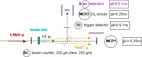
Two event types are currently defined for the LEM experiment: Event 1 is used during setup of the experiment in parallel to Event 2 and measures the time-of-flight (TOF) of the fast muons from the beam counter (BC) to the microchannel plate (MCP1) detector, and the muon decay spectrum on MCP1. The Event 1 TOF spectrum can be easily converted into the energy spectrum of the fast muons. This allows inference on the momentum and momentum spread of the incoming muon beam and therefore serves as a beam monitor.
| Detector | Rates in piE3, before 2004 | Rates in rebuilt µE4, since 2005 |
|---|---|---|
| BC | 3 x 10⁷ /s | 8 x 3 x 107 /s 8 fold segmented |
| TD | 4 x 10³ /s | 3 x 10⁴ /s |
| Sum of e+ | 4 x 10² /s | 3 x 10³ /s |
| MCP1 | 1 x 10⁵ /s | 1 x 10⁶ /s |
Event 2 is for measuring the TOF of the low energy muons (LE-µ) between BC and trigger detector (TD) during setup (low BC rate of the order of 200 kcps/s, measurement of the moun moderation efficiency) and for LE-µSR measurements at full BC rate (30 Mcps): in this mode the TOF is disabled in the Event 2 trigger condition and only the decay positrons are enabled. For beam spot measurements at the sample position a position sensitive microchannel plate detector (MCP2) with delay line anode can be mounted.
The schematics of the NIM trigger logic for both event types can be found here for Event 1, and here for Event 2. The timing scheme for Event 2 is shown here.
The schematics of the NIM trigger logic for both event types can be found here for Event 1, and here for Event 2. The timing scheme for Event 2 is shown here.
Developments
- Replacement of the Nitronic HVS132 for detector high voltages by the PSI high voltage node HVR400 which is part of the Midas slow control bus system ( MSCB). Since the present HVR400 is limited to 2500 V this would require additional development work because several MCP based LEM detectors need higher potentials (up to 5 kV, positive and negative). For these a low ripple less than 30 mVpp is required. Commercial products are available, see, for example, NHQ and DPS modules of Iseg.
- Development of a programmable CFD950 on a VME board with automatic walk adjustment, together with the muSR bulk facility group and the LTP electronics group. In operation since April/2006. Additional VME modules available since 2010: an analog splitter SP950, and a clock divider CD950 (1Hz - 100 MHz). See T. Prokscha et al., A novel VME based muSR data acquisition system at PSI, Physica B404, 1007 (2009), DOI:10.1016/j.phyb.2008.11.206 for more information.
- Use of the CERN HPTDC chip to replace CAMAC TDC's and Ortec picoTimeAnalyzer. LSB is selectable/progammable to 25, 100, 200, 800ps, dynamic range of 100 µs (extendable). Since 2005: use of CAEN's VME TDC (models V1190 and V1290) based on the HPTDC chip with 32 to 128 channels per module and FPGA and DSP on board for data processing. The trigger logic is completely implemented in software since October/2005.
- Use of the object-oriented data analysis package root , that will replace PAW in online/offline analysis.
- Development of musrfit, ongoing. See also A. Suter and B.M. Wojek, Musrfit: A Free Platform-Independent Framework for µSR Data Analysis, Physics Procedia 30, 69( 2012).
- Devlopment of using GPU's for use in fitting and simulations, ongoing.
- Development of a position sensitive detector (Si-pixel, or APD, or SiPM) for decay positrons and surface muons.
- Replacement of bulky light guides and photo-multipliers by AMPD's for readout of plastic scintillators, see LMU Detector Development. In operation since 2010 for the WEW magnet, since 2013 for the AEW magnet ("Bparallel").
- Future option (desire): a multi-purpose, programmable board with Flash-ADC's (1-2 GHz sampling rate on at least 20µs). Do everything you want (CFD, TDC, ADC, ...) on-board in programmable FPGA's.
- The requirements for a new LEM frontend hardware are summarized here.

