
Chopper
The chopper is an essential part for the determination of the neutron energy (see also the section about the basic principle of POLDI). It is essentially a disc rotated at high speeds with some apertures through which neutrons may only pass during certain periods of the discs rotation. This produces a pulsed beam where the 'start time' for each neutron pulse is known.
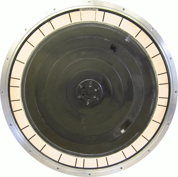
Two disc choppers with a diameter of 700 mm are available at the POLDI facility. One chopper is used for standard applications. It has 32 slits resulting a 5.8% duty cycle. Eight pseudo-randomly distributed distances between the slits are repeated each quarter round (see figure 1). Additionally a one-slit chopper is available for applications where pulse overlapping has to be minimized or excluded. The entrance slit of the chopper and the slits in the chopper itself have a width of 4 mm and a height of 35 mm. The chopper speed can be set until 15000 rpm. Because of resonances some speed ranges are not valid.
Optics
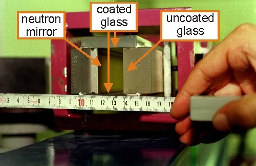
The small chopper slit is imaged onto the sample position by an elliptical neutron mirror in order to minimize the loss of neutrons (see figure 1). The distance between chopper and sample is 11.8 m and the length of the neutron mirror is 6 m. The neutron mirror forms one side of the neutron guide. The mirror itself and the top and bottom plates have a super mirror coating with a maximum reflecting angle of 3 times that of natural Ni. The glass plates on the opposite site of the mirror are non-reflecting.
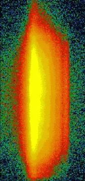
Figure 2-2 displays a 2D image of the intensity profile of the beam at the sample position. The beam profile is asymmetrical due to the cut off at the inner side of the neutron mirror.
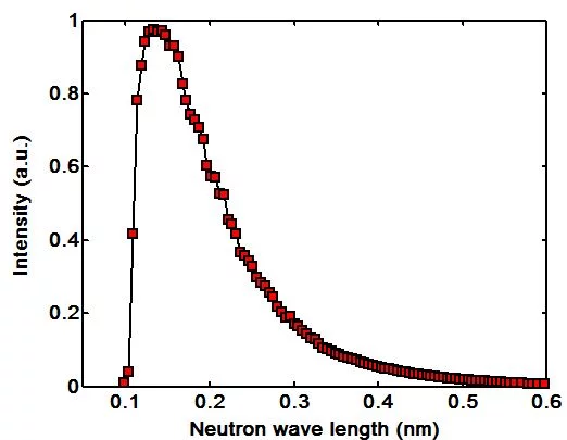
The neutron wavelength distribution at the sample position is shown in figure 2-3. Note the sharp cut-off of the intensity at about 1.1 Å which is a property of the neutron mirror. The beam collimation can be adjusted with a diaphragm at the end of the mirror 2.9 m in front of the sample, the beam size and position can be selected with a second diaphragm close to the sample (see also instrument description).
Collimators
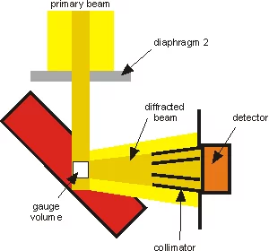
The collimator together with diaphragm 2 defines the sampled gauge volume. This is demonstrated in figure 1. Diaphragm 2 determines the gauge volume in two directions. It is mounted at an optical bench. Due to the horizontal and vertical beam divergence (±1°) it is recommended to minimize the distance between slits and sample. If the diaphragm 2 cannot be fixed close to the sample, the vertical divergence can be reduced by mounting of an additional slit or small collimator between neutron guide and monitor, or an additional slit after the diaphragm.
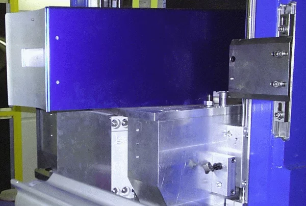
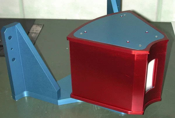
The third dimension of the gauge volume is determined by the radial collimator. An overview of the available collimators at POLDI is given in the table below. The collimators with an acceptance of 1.5 mm and 3.8 mm are permanently installed at the collimator holder (see figure 3-2), whereas an 0.6 mm collimator can be installed at the front side of the collimator holder (see figure 3-3). All collimators have an angular range of 30°. The transmission functions of these three collimators are close to a triangle shape, as demonstrated in figure 4. The collimators have a quite large distance to the gauge volume. This allows, in combination with the well collimated primary beam to investigate also large samples and keeping still a good spatial resolution.
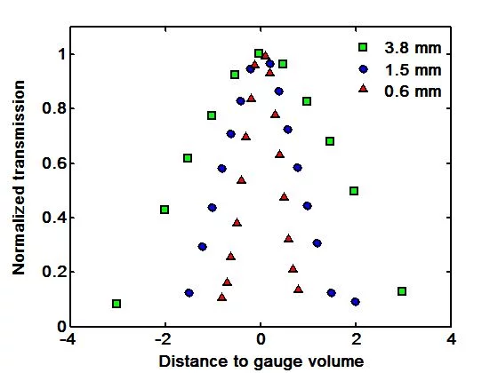
| Collimator | FWHM (mm) | Distance to specimen (mm) | Transmission (%) |
|---|---|---|---|
| 1 | 3.8 | 410 | 78 |
| 2 | 1.5 | 230 | 74 |
| 3 | 0.6 | 70 | 72 |
Detector
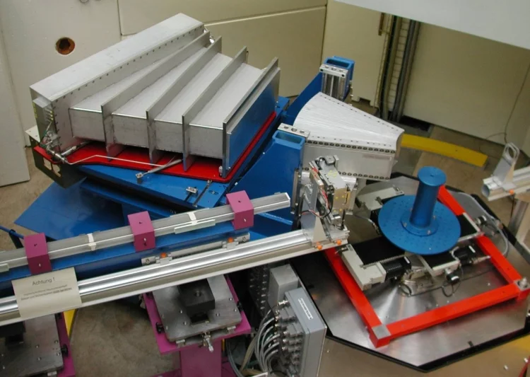
The diffracted neutrons are detected with a one-dimensional position sensitive 3He-detector. It consists of 400 cells each with a width of 2.5 mm. Figure 4-1 displays the detector without shielding
Detector characteristics
- The detector-sample distance is about 2 m.
- Neutrons scattered in an angular range of 30° are being accepted.
- Two positions - 90 and 105° (detector centre) are available.
- The detector is positioned in time focusing condition in order to avoid loss in time resolution due to the thickness of the 3He chamber.