Optics Hutch
A side view of the optics hutch in shown in Figure 1. Again, the components in the optics hutch can be divided into subgroups according their function.
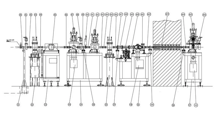
Figure 1: Components in optics hutch.
Components for Spatial and Spectral Refinement of the X-ray Beam
- filter unit for pink beam and flux reduction (A10)
- double slits assembly (A6)
- toroidal mirror (A10)
- double crystal monochromator (A24)
- fast valves (A14, A30)
- bremsstrahlungstopper (A26)
- shutter-stopper assembly (A34)
- diagnostic chamber (A12) hosting a photon beam position monitor
- fluorescence screen (A17)
- photon beam position monitor (A32)
Beamline Geometry
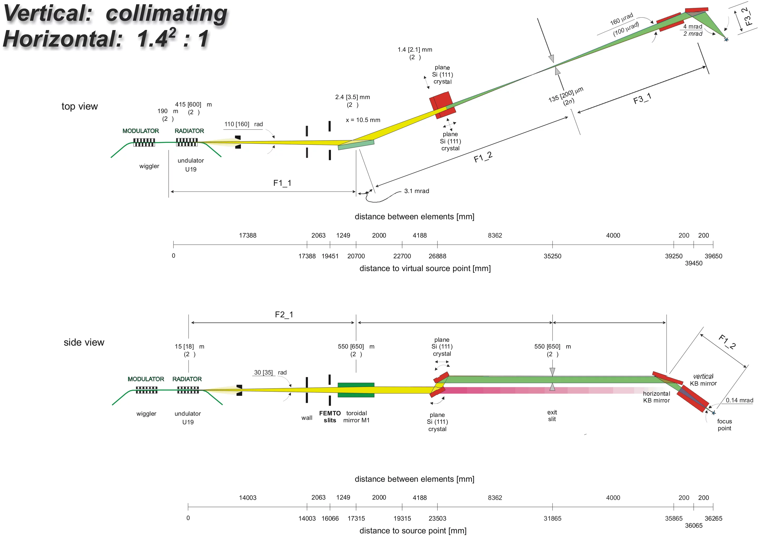
Figure 2: Beamline Geometry.
Mirror
The mirror corresponds to the first key optical component within the beamline design. The mirror unit serves three main purposes:
- to collimate the beam in the vertical dimension
- to produce a 1.4:1 image in the horizontal dimension,
- to act as a low-pass filter with an energy cut-off of ~22keV.
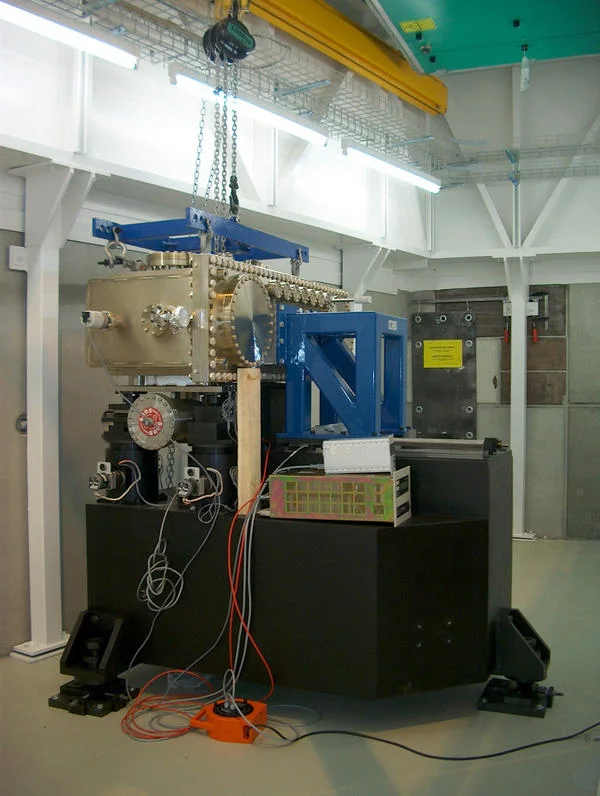
Figure 3: Installation of microXAS mirror tank.
Such a step-wise reduction in x-ray spot size offers two main advantages: First, the capability of dynamical focusing and second, optimizing the overall acceptance of the optical system. By using just one mirror, the required focusing characteristic can be achieved by means of a toroidal mirror shape. The toroidal figure will be produced by bending a cylindrical mirror into the shape of a toroid.
Concerning low-pass filter characteristics, the upper energy cut-off will be determined by the grazing angle of incidence in combination with the mirror coating employed. For the microXAS mirror system, an angle of incidence of 3.1 mrad and a Rh coating is foreseen. This combination yields a reduced transmission for x-rays with energies higher than approximately 22 keV.
As a specialty, the mirror will deflect sideward. Although more demanding from an engineering point of view, such a mirror orientation results in an important suppression of the spot size broadening due to figure errors [4, 8].
The current design foresees that the same mirror is also used for the redirection of the X-rays in the FEMTO project. This requests for the possibility of a relatively fast change between two well-defined positions of operation. Due to the high restrictions concerning spatial beam stability the mechanical stability and the request for maintaining tight mechanical tolerances are critical.
At present, the mirror system (with a total unit weight of more than 3 tons!) is being installed at the microXAS beamline (Figure 3).
Monochromator
The source size at SLS is small and the double crystal monochromator (DCM) is located at quite a distance (10 m) from the intermediate focus point in the experimental hutch. These facts put very drastic constrains on the stability of the DCM (A24).
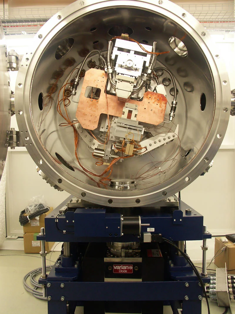
Figure 4: Monochromator.
To maintain a fixed height offset and a fixed angle with respect to the incident white beam during an energy scan the monochromator needs to operate with a fixed vertical offset. For the second crystal fine-tuning the angular offsets with respect to the first crystal is required and thus, every design consideration for the DCM should be given to maintaining the angular stability. Furthermore, for maintaining a fixed offset in height relative to the incident beam during energy scanning, the second crystal also needs to be translated in the direction normal to the crystal plane.
In order to meet the stringent requirements on the relative accuracies between the two crystals we have chosen a double cam design from Kohzu Co. that offers a good parallelism and stability when scanning over a large angular range as required for microbeam XAS. In a double cam system the first and second crystal holders are mounted on the same rotating table of the Bragg axis goniometer. Crystal translations, which are necessary in order to keep the beam hitting the center of each crystal and beam offset fixed, are provided through mechanical link to rotation of the main Bragg axis by two cams. Therefore, any change of energy or Bragg angle can be performed by actuating just one motor (placed outside of the vacuum chamber), while the exit beam runs parallel with the incident beam with constant offset independently on the Bragg angle. The fixed-exit monochromator will be equipped with two sets of monochromator crystals, namely Si(111) and Si(311), allowing to optimize the experiments with respect to photon flux or energy resolution. Due to the power density impinging on the first monochromator crystal liquid nitrogen cooling is required. The LN2 cooling will be performed by a closed loop system from Messer Co. The experience with an identical cooling system at SLS has shown that the flow of liquid nitrogen does not introduce any noticeable vibrations.
In order to meet the stringent requirements on the relative accuracies between the two crystals we have chosen a double cam design from Kohzu Co. that offers a good parallelism and stability when scanning over a large angular range as required for microbeam XAS. In a double cam system the first and second crystal holders are mounted on the same rotating table of the Bragg axis goniometer. Crystal translations, which are necessary in order to keep the beam hitting the center of each crystal and beam offset fixed, are provided through mechanical link to rotation of the main Bragg axis by two cams. Therefore, any change of energy or Bragg angle can be performed by actuating just one motor (placed outside of the vacuum chamber), while the exit beam runs parallel with the incident beam with constant offset independently on the Bragg angle. The fixed-exit monochromator will be equipped with two sets of monochromator crystals, namely Si(111) and Si(311), allowing to optimize the experiments with respect to photon flux or energy resolution. Due to the power density impinging on the first monochromator crystal liquid nitrogen cooling is required. The LN2 cooling will be performed by a closed loop system from Messer Co. The experience with an identical cooling system at SLS has shown that the flow of liquid nitrogen does not introduce any noticeable vibrations.