The GDP-spectrometer is equipped with several computer controlled motor drives.
The new system uses 3-phase stepping motor drives (BERGER/LAHR). It is based on PSI-standard
hardware developed by the Electronics and Measuring Systems Group and is remotely controlled by the
MIDAS slow control system
DELTAT.
The applied components have been used for many years in the Laboratory for Neutron Scattering LNS.
Important Note: All motor drives are equipped individually with limit switches and all drives usually can be moved safely between this limits. But his may not be the case for the spectrometer drives in the your present setup. Movement of the cryostat table, e.g., could damage the spectrometer components if the UP/DOWN-detectors are in place. Please first check carefully inside the area if the desired components can move safely. Check also cables and other parts and switch off all motor drives that you don't need (see below). Be always aware of possible movements when you manipulate anything on the spectrometer. Somebody could sit in front of a remote computer and play with the motor drives!
The main components of the control system are located in a yellow rack in the area:
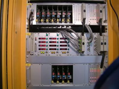
Stepper motor drive control electronics.
It consists of a power electronics unit for motors 1 to 8 (top row), a motion control and position read back unit (central row) and
a power electronics unit for motors 9 to12 (bottom row). Only channels 1 to 6 are used at present, channel 7 to 12 are for
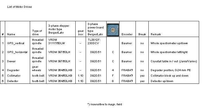
future development. Remark: the power board of motor 1 is of a different type (Berger/Lahr TLD012F: 230DCV) and is located on the rear of the rack.
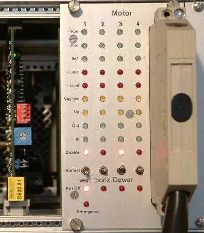
Stepper motor drive status display & safety switch array,
power board 8 (left) type D920.51 (Berger/Lahr).
power board 8 (left) type D920.51 (Berger/Lahr).
Each axis has a column of status display LEDs and a motion control switch. Motion of a motor drive is possible only if the
corresponding switch is in the 'Normal' position.
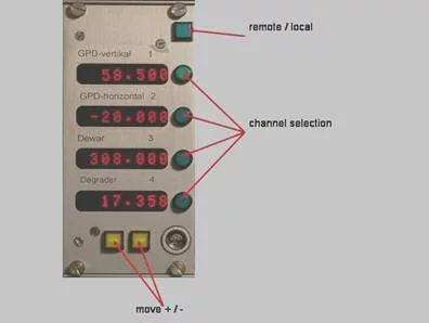
Stepper motor control & display unit.
The display units for all channels are in mm except for the degrader which is in Degrees (see below).
To operate proceed as follows:
To operate proceed as follows:
- Stop front end 'smngpd' on DELTAT. Remark: DELTAT will take control of the motor
- Select the 'Normal' position on the safety switch of the channel to be used (LEDs 'Disable' and 'Pwr. Off' not lit).
- Hold down the remote/local controller button of the left control & display unit for a few seconds until the move+/- button (yellow) switch on.
- Select the channel by pressing one of the channel selection buttons.
- Use the move +/- buttons to move the selected motor drive to the desired position. Remark: Holding down the corresponding channel selection button while pressing 'move +/-' will result in high speed movement which makes sense especially when the cryostat table is moved out completely.
The GPD-stepper-motors are controlled from DELTAT using
An example for an Autorun command is
Modify Devices... smngpd... An example for an Autorun command is
SET smngpd GPD_VERTICAL 60
Note:
The units for the 'Degrader' are degrees because it consists of two wheels of variable thickness rotatable with respect to each other.
The possible angular range of the drive is -20...+380o. In the range below 30o and above 330o
the degrader thickness is inhomogeneous over the beam size. This is due to the wedge shape of the degrader wheels
and a hole for zero degrader thickness details).
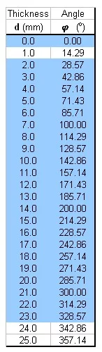
Degrader thickness vs Angle, useful range: blue.
Alternatively the formula d = 0.07xφ can be used.
Alternatively the formula d = 0.07xφ can be used.
-- Main.AlexAmato - 13 May 2014