Laser Structuring

Lasers can be used to directly structure a wide range of materials, if the right wavelength and power-density is used. Due to the high cost of laser photons, it might be more effective to use a combination of laser structuring and alternative methods (e.g. reactive ion etching). If the target materials is transparent for the selected wavelength, indirect structuring methods (such as laser induced backside wet etching) have to be used.
Fabrication of micro-optical elments in Polyimide:

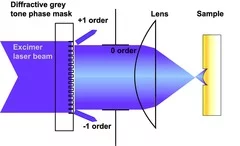
The intensity of a XeCl excimer laser is modulated by the Diffractive Grey Tone Phase Mask (DGTPM, in collaboration with the X-ray Optics and Nanomagnetism group at PSI). The beam is then imaged onto the polymer surface with a 5 times demagnification using a doublet lens. A two-dimensional Fresnel micro-lens array was fabricated in the polyimide by moving the sample and repeatedly exposing the DGTPM which encodes the Fresnel lens shape.
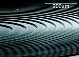
SEM picture of a micro-lens array in Durimide. The size of each micro-lens is 900 × 900 μm.
Gratings with a Spacing of 1.09 μm in Trianzene Polymer:

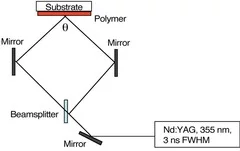
The spacing of the grating, $s$, can be varied according the equation,
$s=\frac{\lambda}{2 n \sin{\theta}}$ by changing the intersection angle.
AFM image of grating of 1090 nm spacing. One pulse with 80 mJ/cm2 and the X-Z plot, showing the symmetric spacing grating depth.
Micro-cogwheel in PEC:

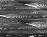
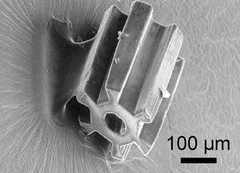
SEM image of a micro-cogwheel in Poly(esther carbonate). The cogwheel has a diameter of 200 μm and has been produced from a ca. 250 μm thick polymer layer by scaning with a 10 μm laser spot and an irradiation wavelength of 308 nm.


(in collaboration with the Fuel Cells in ENE)

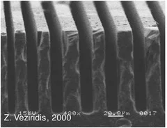
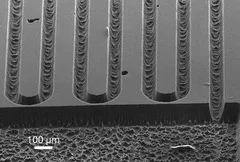
New structuring methods for various materials are required to decrease the size of components for different devices. One possible application are glassy carbon electrodes for polymer electrolyte fuel cells.
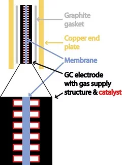
Standard polymer electrolyte fuel cells (PEFC) designs require many components: a flow field for gas supply, a gas diffusion electrode carrying the catalyst, the proton conducting membrane and a surrounding gasket. For micro fuel cells (μFC), the number of components can be significantly reduced by using a catalyst coated well-conducting material for the flow field. These well-defined structures serve as models for studying the transport of H+ and the surface mechanisms of catalyst utilization. Also the influence of the flow field design on the gas flow is investigated.
Alternative Structuring Methods:
  1. Micro-sawing
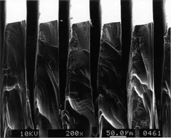
    • simple method, well-defined side walls
    • sequential machining (slow)
    • straight structures only
    • sealing at the sample edges is required
  2. Laser Ablation
    • simple method
    • flexible
    • sequential machining
    • poorly defined channel bottoms and walls
Novel Structuring Method:
Combination of Laser Ablation & Reactive Ion Etching
  1. Processing stages:
    • metal film deposition
    • laser structuring
    • Reactive Ion Etching
    • Cleaning
  2. Reactive Ion Etching (RIE):
    The oxygen plasma removes the glassy carbon (GC) in the unmasked areas. RIE combines chemical etching (reactive O) and physical etching (ion bombardment by O2+) and yields high etch rates and good aspect ratios. These high etch rates are always accompanied by pronounced mask erosion, which leads to tapered side walls. A mask material with low etch rate and good adhesion is therefore required.
  3. Electrochemical Characterization:
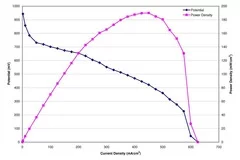
    • Comparison of different concepts for a fuel cell containing little single parts: A catalyst-coated membrane surrounded by two microstructures vs. a membrane surrounded by catalyst-coated microstructures
    • Optimization of the flow fields to minimize the pressure drop, to maximize the water removal and to obtain a maximum power density
    • Investigation of catalyst utilization on defined electrode structures
    • Methods: Polarisation Curves, Electrochemical Impedance Spectroscopy, Hydrogen Under-Potential Deposition


The miniaturization of optical elements is one of the key technologies in modern optics. Arrays of Fresnel lenses fabricated by a multi-step process in quartz or in CaF2 are e.g. applied as beam shapers for high power excimer and Nd3+:YAG lasers. An alternative technique for the fabrication of micro-lenses in UV transparent materials combines laser induced backside wet etching and projection of Diffractive Gray Tone Phase Masks (DGTPM, in collaboration with the X-ray Optics and Nanomagnetism group at PSI). This one step process allows precise structuring of CaF2, BaF2, quartz and sapphire with a XeCl excimer laser and fluences well below the damage threshold of these materials.

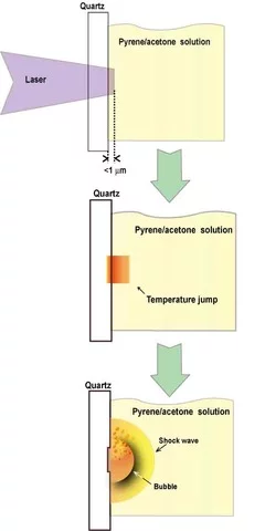
LIBWE Process
  1. Strong absorption of intense UV light by an organic solution in contact with the UV transparent material.
  2. The non-radiative decay of excited organic molecules creates a high temperature jump (> 2000 K) at the substrate-liquid interface.
  3. The fast thermal evaporation of the solution results in the generation of a shock wave and boiling of the solution. The expanding shock wave and the growth/collapse of the bubble generate a pressure jump, which removes the molten material from the surface.
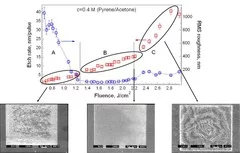
The etch rate and roughness of quartz by LIBWE using a 0.4 M pyrene in acetone solution as “etchant“ and a XeCl excimer laser (308 nm, 30 ns) as irradiation source are shown above. The LIBWE mechanism reveals a complex behavior, which consists of a formation of carbon deposits at the low laser fluence range (marked as A), melting of quartz and smooth mechanical removal at the intermediate fluence range (marked as B) and plasma assisted etching at the high laser fluences (marked as C).
Fabrication of microoptical elements in UV transparent materials by LIBWE and projection of DGTPM

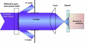
The diffractive gray tone phase masks are used to modulate the laser beam intensity. They are fabricated by e-beam lithography and reactive ion etching. The modulation of the laser light intensity, which is projected onto the sample is obtained by changing the line width in the DGTPM.
Setup for the fabrication of microoptical elements by a combination of LIBWE and DGTPM
3D profilometer scan of a Fresnel lens etched in BaF2 (A) and plano convex micro-lens array fabricated in quartz (B).
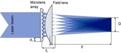
Concept of beam homogenizing by a micro-lens array

The homogenized beam size D obtained at the focal plane of the collecting lens is proportional to the focal length of the collecting lens, the diameter and focal length of the micro-lens, and can be calculated using Equation:
$D=\frac{d_{ul}F}{F_{ul}}$ where $d_{ul}$ and $f_{ul}$ are the diameter and the focal length of the micro-lenses, and $F$ is the focal length of the collecting lens.
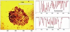
Quadrupled Nd:YAG (266 nm, 5 ns) laser beam profile visualized by ablation of polyimide, without beam homogenizer.
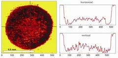
Quadrupled Nd:YAG (266 nm, 5 ns) laser beam profile visualized by ablation of polyimide, with beam homogenizer.