
The POLDI load frame has a load capacity of maximal 30 kN. Measurements in horizontal and vertical position (figure 1) are possible. This allows measuring the lattice strain evolution both parallel and perpendicular to the tensile axis (axial and transverse strains).
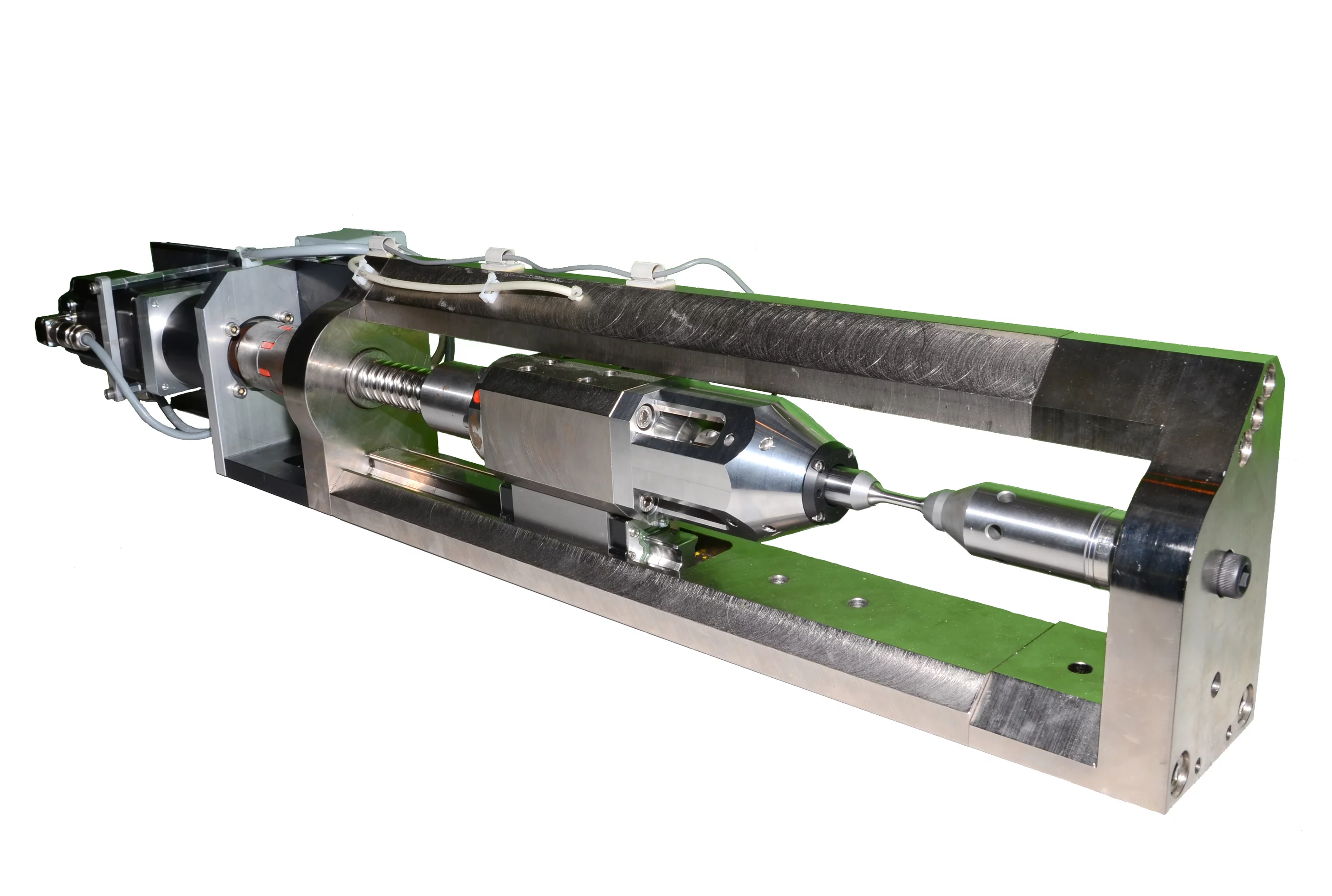
Neutron collection can be performed under constant load or constant displacement conditions, or a combination of both.
Several samples geometries are possible:
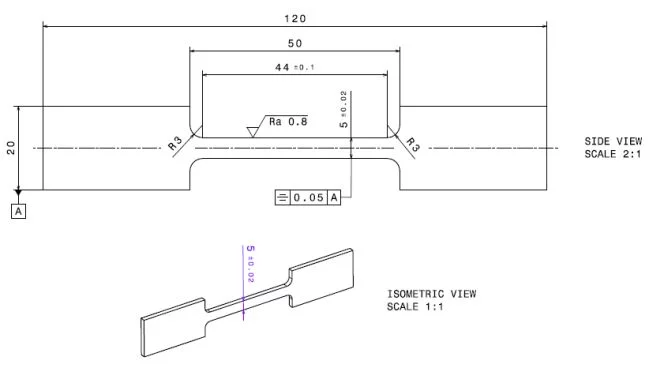
Flat (maximum 10kN)
The deformation rig is equiped with Mark-10 Test Grips (Dynamic Measurement Systems LLC, G1012-1) for mounting flat specimens (see for instance figure 2, technical drawing). For measurements in horizontal position a minimum gauge length of 44mm is recommended (for samples with shorter gauge length the diffracted neutron beam might be partly shadowed by the tensile grips).
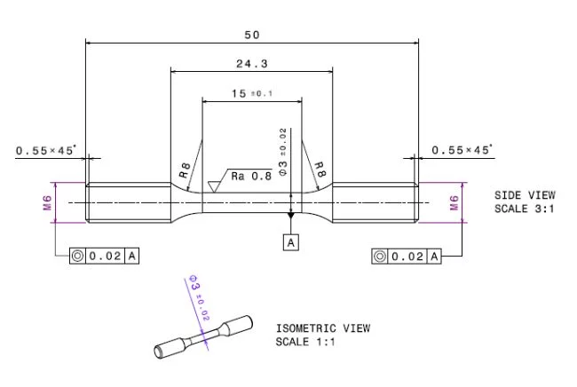
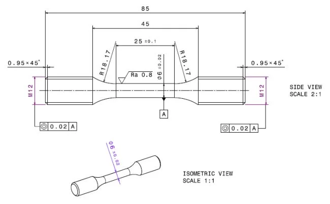
Round (maximum 30kN)
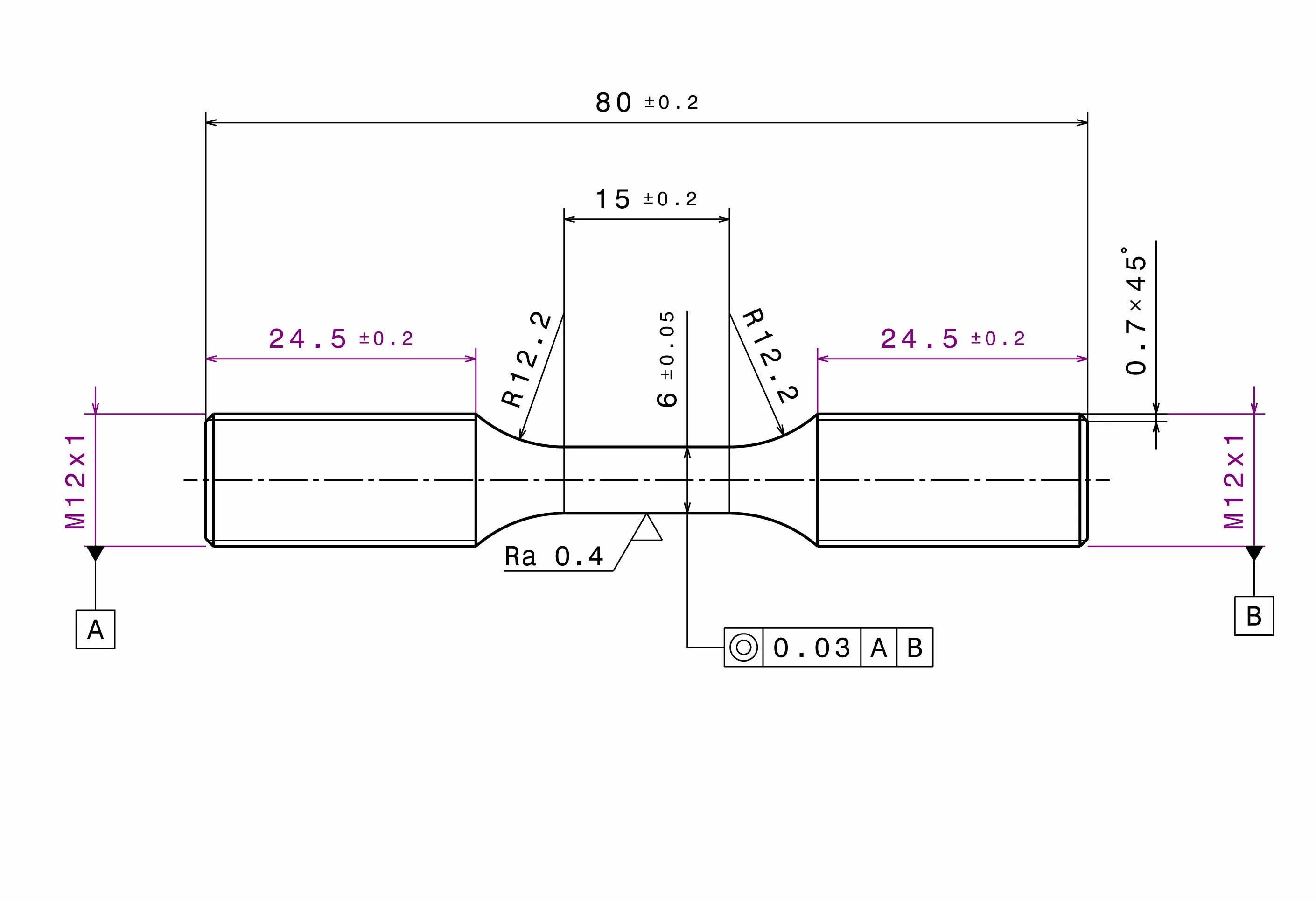
The tensile rig supports M6 (technical drawing) and M12 (technical drawing, or for fatigue): Example of a round fatigue specimen with M12 thread.) threaded tensile specimens, as shown in figures 3 and 4, respectively. The gauge length of the specimens shown in these figures are minimum values only. To determine the appropriate sample geometry take following considerations into account:
- One cannot exceeded the maximum force of 30kN
- Ideally the gage volume sampled by neutrons should be fully immersed in the sample. For instance, for the combination of a 2mm wide incoming beam and the 1.5mm radial collimator the minimum sample diameter would be 2.5mm.
- In case the strain is measured with an axial extensometer take into account that possible gauge lengths and travel ranges are restricted (see below).
For other types of specimens (such as wires, compression samples, ...) contact one of the beamline scientists
Currently three methods for strain measurements are available:
Clip-on axial extensometer
Two high precision axial extensometers are available. The properties are given in the following table. Both extensometers can be used for the sample geometries listed above.
| Type | Gage length | Maximum travel | Maximum strain | Data sheet |
|---|---|---|---|---|
| MTS 634.12F-25 | 25 mm* | +12.5mm / -2.5mm | +50% / -10% | Data sheet (external link) |
| MTS 632.26F-20 | 8 mm | +/-1.2mm | +/-15% |
* A gage length extender up to 50mm is also available.
Strain-gaged flexures
Strain-gage flexure attached to the sample can be read out using the NI USB-9219 Universal Analog Input Module. Quarter, half, and full-bridge gages can be used. Note that strain gaged flexures are not available at the beam line and should be mounted by the user before the start of the experiment.
Optical digital camera
The tensile rig is equiped with a NI 1764 Smart Camera. Strain measurements can be performed by measuring the distance between two markers or by image correlation. Contact the instruments responsibles to find out which solution is appropriate for your samples.