
The in-situ surface diffractometer
The in-situ surface diffractometer (ISSD) is from Micro-Controle Newport, France.
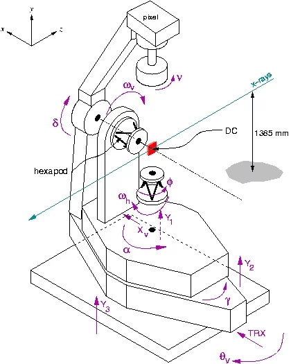
The design is based on that suggested by Elias Vlieg [E. Vlieg, J. Appl. Crystallogr., 31, 198 (1998)] and has 2 circles [a and w v (vertical geometry) or w h and f (horizontal geometry)] associated with the sample movement, and three (d, g, and n) for the detector. The diffractometer can be operated in two modes, either with a vertical, or a horizontal sample surface orientation. In the former mode, the diffractometer can support small environmental chambers connected to the hexapod only, up to 25 kg weight, or large chambers up to 500 kg, supported by the large a-table. In the horizontal mode, stand-alone chambers can be mounted on the hexapod with weights up to 200 kg. Angle calculations and modes of operation peculiar to the use of the PILATUS 100k pixel detector can be found here.
Motor | SPEC name | Description |
|---|---|---|
a | alp | angle of incident x-rays in the vertical mode (VM); unused in horizontal mode (HM) |
wv | ov | rotation of sample about normal to its surface in VM; unused in HM |
wh | oh | angle of incident x-rays in HM; unused in VM |
f | phi | rotation of sample about normal to its surface in HM; unused in VM |
xv | xv | translation of the entire hexapod stage in VM; unused in HM |
g | gam | rotation of detector arm in horizontal plane |
d | del | rotation of detector arm in vertical plane |
n | nu | rotation of pixel detector and slits around detector axis |
Y1, Y2, Y3 | y1, y2, y3 | tilting of entire diffractometer. Use with caution! |
TRX | trx | translation of entire diffractometer. Use with caution! |
qv | thetav | rotation of entire diffractometer. Use with caution! |
All these motors can be easily moved and scanned using SPEC commands. | ||
If the user needs to realign the diffractometer, he/she should first home all the relevant motors in SPEC (do NOT home outside the SPEC environment!) using the command "home mot" (e.g., to home ALPHA, type in SPEC: home alp).
| Motor | DIAL value | [mm/deg] |
|---|---|---|
| ALP (V) | -15.769 | +/- 0.005 |
| DELTA | -0.1212 | +/- 0.005 |
| GAMMA | 2.1883 | +/- 0.005 |
| NU | -57.40 | +/- 0.02 |
| Y1 | -9.1100 | +/- 0.025 |
| Y2 | -4.4546 | +/- 0.025 |
| Y3 | -6.2299 | +/- 0.025 |
| TRX | -4.785 | +/- 0.05 |
| THY | 0.000 | +/- 0.001 |
Using the procedures detailed in the "how to SD manual", the beamline scientist (Phil Willmott) has obtained DIAL values to use for positioning the motors at zero (the motors XV and OMEGAV are missing, because they depend on the sample mounting, which will in general be different for each sample. Motor ALP is for the vertical geometry only, motor OMEGAH is for horizontal geometry only). The most recent alignment procedure was carried out on 5th June 2008 using a laser tracker. The horizontality of the diffractometer (the ALPHA movement) is accurate to 0.001o, while the absolute (DIAL) values of the Y1, Y2, and Y3 motors is accurate to better than 0.02 mm. Here are the latest values:
An AutoCAD drawing of the diffractometer (using SolidWorks) can be downloaded here (2.3 MBytes!), which can be used to check dimensions of any chamber or equipment to be mounted on it.
The hexapod
The hexapod is from Physikinstrumente and is used to finely adjust the position of the sample to the center of the diffractometer and to align the surface normal, using three translational pseudo motors x, y, and z, and three angular pseudo motors u, v, and w.
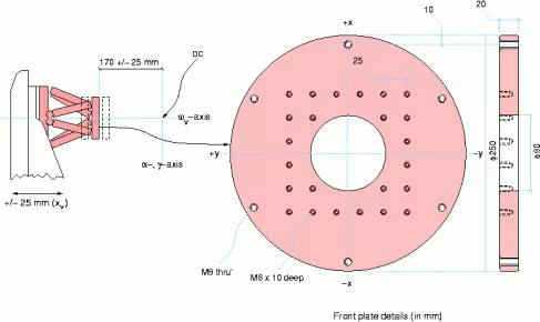
In both the vertical (shown left, in pink) and horizontal configurations, the distance between the front plate of the hexapod and the center of the diffractometer (DC) is 170 mm. The hexapod movements allow that the hexapod front plate can move forwards, backwards, left and right, by 25 mm, and, in the vertical configuration, the entire hexapod mounting plate can also be translated by +/-25 mm, using the xv motor.
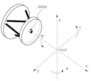
Details of the dimensions of the hexapod front plate are also shown. On the right, the relative Cartesian pseudo motors x, y, and z, plus their respective rotations, u, v, and w, are shown. The arrow heads indicate positive movements.
The hexapod has three translational degrees of freedom - x, y (shown), and z (perpendicular to the hexapod plate) and three rotational degrees of freedom, u, v, and w, rotating around the x-, y-, and z-axis, respectively. The point of rotation of the hexapod u, v, and w motions (the "pivot point") is defined as the point in space using the cartesian coordinates r, s, and t (given in mm) away from the center of the back plane of the front plate. Hence, if it is required that the sample rotates around the center of the diffractometer (as is most usual), one should nominally set rst to 0, 0, 190 (190 = 170 + 20).
Normal absolute movements of the hexapod can be executed from SPEC using the commands
- hmvx < value> - movements in the x-direction
- hmvy < value> - movements in the y-direction
- hmvz < value> - movements in the z-direction
- hmvu < value> - rotation around the x-axis
- hmvv < value> - rotation around the y-axis
- hmvw < value> - rotation around the z-axis
while relative movements are executed in SPEC using the commands
- hmvxr < value> - movements in the x-direction
- hmvyr < value> - movements in the y-direction
- hmvzr < value> - movements in the z-direction
- hmvur < value> - rotation around the x-axis
- hmvvr < value> - rotation around the y-axis
- hmvwr < value> - rotation around the z-axis
The present positions of the hexapod can be called from SPEC by the command hexaShow
The r-s-t pivot position can only be adjusted outside SPEC. In a shell of the control computer pc5758, type in hexapod. You have now entered the external python hexapod control script. Type in rst 0 0 190, if for example, you want the pivot point to be 190 mm in front of the hexapod plate and on the rotation axis.NOTE: It is important that the r-s-t values are set prior to adjusting x, y, z, u, v, and w.
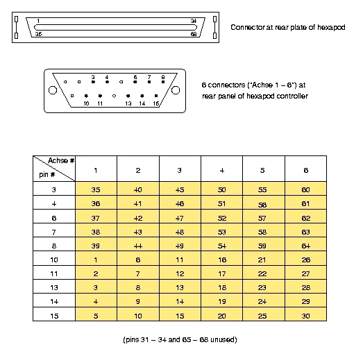
Below is a figure and table detailing the connector pins for the cabling between the hexapod and the hexapod controller
Troubleshooting
The hexapod can freeze. This is evident from hexapod movements sent via SPEC seeming to take indefinitely long. If this happens, turn OMEGAV to zero (if in the vertical geometry), and enter the experimental hutch. To the right of the tall rack, there is a smaller rack containing the Newport MM4006 controllers. Above this is the hexapod control computer. Press CTRL-ALT-DEL, which reboots the computer. This will boot up the hexapod control software as default. Once the hexapod schematic is shown on the screen, type in i. This should initialize the hexapod. The success of this command is seen by six fields, [1] through [6], representing the 6 hexapod motors, appearing over several seconds. If this does not happen, the hexapod is still frozen. Try turning off the hard disk (located at the very bottom of the rack on which the hexapod screen is sitting), and repeat the above procedure. Also check that OMEGAV really is at 0o, for which the -x direction points upwards, and that nothing is obstructing movement of any of the six pods
More detailed notes on software control of the hexapod can be found in SD Computing
Filter choices
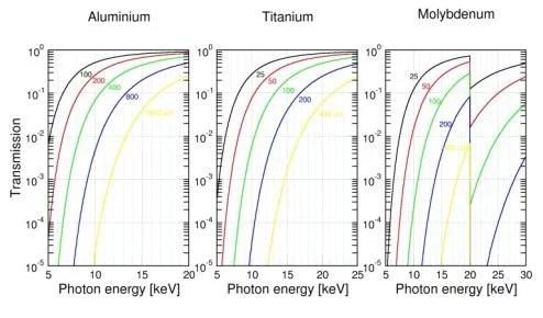
Fifteen filters are used for beam attenuation and provide sensible steps over the entire range of available photon energy. Below are transmission plots of Al, Ti, and Mo over the relevant energy ranges, plus a table of the filter thicknesses, accurately calibrated at 19.5 keV. A sixteenth filter slot is reserved for an array of micron-sized holes in a tungsten plate and can be used to quantify the beam divergence. A filter widget allows one to automatically change transmission by any desired amount using a lookup table. Automatic filter changing during scans is possible in our flavour of SPEC, and is described here
| Filter position | Filter material | Thickness [microns] |
|---|---|---|
| 1A | Al | 105.8 +/- 0.6 |
| 1B | Al | 209.8 +/- 1.2 |
| 1C | Al | 419.6 +/- 1.5 |
| 1D | Al | 825.3 +/- 0.8 |
| 2A | Al | 1649 +/- 2.0 |
| 2B | Ti | 23.45 +/- 0.10 |
| 2C | Ti | 46.37 +/- 0.18 |
| 2D | Ti | 92.73 +/- 0.13 |
| 3A | Ti | 185.2 +/- 0.30 |
| 3B | Ti | 348.1 +/- 0.40 |
| 3C | Mo | 25.4 +/- 0.20 |
| 3D | Mo | 50.73 +/- 0.30 |
| 4A | Mo | 102.95 +/- 0.6 |
| 4B | Mo | 204.4 +/- 0.60 |
| 4C | Mo | 406.9 +/- 1.0 |
| 4D | unused | --- |
NOTE: Because Mo has a sharp change in its transmission at 20.000 keV, this energy (+/- 20 eV) should never be used in conjunction with the Mo-filters, which must be disabled if this energy is used. Otherwise, the given values for the transmission of the filters are exceedingly unreliable!
Substrate holder
Many experiments require a mount for a substrate. It is recommended to use the "Swiss Stubb" design described below if at all possible - it is used at several of the other beamlines at the SLS and also many other scientific institutes within Switzerland. Importantly, it is also compatible with the in-house PLD growth chamber and the ambient condition chamber described in this website. A technical drawing of the dimensions (in mm) of the connecting foot is given here.
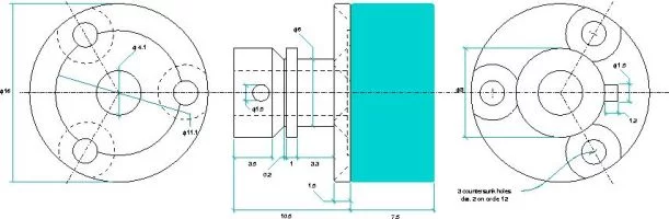
Bayonet foot design for the "Swiss Stubb" substrate holder. The substrate is mounted on a block heater or other mechanism (shown in green). The block must have an outer diameter no greater than 16 mm and, ideally, a height of 7.5 mm (including the thickness of the substrate itself). Contact Phil Willmott for more details and possible designs for the block heater.
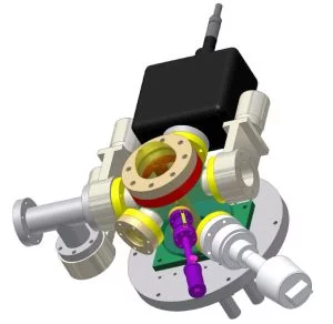
Cryo chamber
A cryogenic chamber is available for investigating materials between 14 and 480 K. The chamber presently has an ultimate pressure of 10-5 mbar. It can be operated with either two concentric Be-domes to obtain the lowest possible temperature, or with a single dome for less stringent applications.
Mini chamber
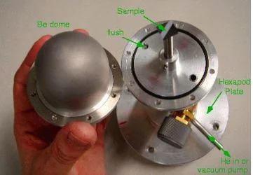
The inner dome of the cryochamber (radius 25 mm) can also be mounted on a small plate/o-ring system and either flushed with He or pumped for simple inert sample environment applications. Experience has shown that even highly chemically stable metal oxides samples deteriorate over several hours if exposed to focussed x-rays in air. By keeping them in a modest vacuum or He-atmosphere, their lifetime is extended to at least several days.
SD hutch webcam
The webcam in the SD hutch is mounted on top of the large controls rack and can be accessed here
X-ray eyes
Two x-ray eyes are available in the SD experimental hutch. The first XRE (left image, below) is fixed permanently on a bracket on the far wall of the hutch.
THIS SHOULD NEVER BE DISMOUNTED OR SHIFTED!! It is connected to a video screen in the control hutch, on which a blue dot has been drawn. This is the reference anchor point for aligning the focussed beam using the roll motor of the second DCM crystal and the pitch (downstream) motor of Mirror II. The field of view is approximately 6 x 4.5 mm. The second XRE is portable and mounted on a bracket mount (right image, below). This can be fixed as near as possible to the sample on the diffractometer to optimize the focussing (vertical: Mirror II bender; horizontal: Sagittal bender of second DCM crystal). The XRE is connected to PC4410 in the Controls Hutch via a firewire cable, and image capture is achieved using the FlyCap.exe program on the Desktop. The field of view is approximately 3 x 2 mm.