
General description
The surface diffractometer is equipped with a pixel detector constructed by the SLS detector group. This second-generation PILATUS II detector was installed in October 2005 (see Figure below) and uses photon-counting technology with essentially no background noise.
Specifications
| Spec. | Value |
|---|---|
| Active area | 487 x 195 pixels (= 95 kPixel) |
| Pixel size | 172.0 mm x 172.0 mm |
| Dynamic range | 106 (220) |
| Maximum count rate | 106 cts/s |
| Location | 1140.8 +/- 0.25 mm from the centre of the diffractometer (gamma axis) |
| Subtended angle | 4.205o x 1.684o (0.008634o/pixel) |
Mounting
The detector is mounted on the delta arm with its center nominally along the nu-rotation axis. The detector can, however, be shifted laterally both up/down and sideways using positioning screws on the detector holding bracket.
The detector flight tube has 3 extension pieces of lengths 200, 100, and 50 mm. When all three pieces are used and a compact detector 4-slit module is mounted on the front, the slit module is approximately 60 mm from the center of the diffractometer.
The detector flight tube has 3 extension pieces of lengths 200, 100, and 50 mm. When all three pieces are used and a compact detector 4-slit module is mounted on the front, the slit module is approximately 60 mm from the center of the diffractometer.
The 100 kPixel Pilatus II detector setup. The flight tube length can be varied in steps of 50 mm between 725 and 1075 mm, using any combination of the three extension tubes (50, 100, and 200 mm).
Back to top
Back to top
Radiation protection system
At the front of the detector flight tube of the diffractometer is a housing containing horizontal and vertical slits, a slow (2mm-thick steel) removable beam stop plate, and a mini ionization chamber. The purpose of the mini-IO is to monitor whether too much radiation (e.g., full focussed beam) is incident on the pixel detector, which can then trigger the fast photon shutter to close if a threshold value is exceeded.
Inadvertent experiments testing the radiation hardness of Pilatus II have shown it to be remarkably robust. However, we know that a few seconds exposure with the full beam can lead to permanent damage. This should of course be avoided at all costs, but human error, particularly at 2 o'clock in the morning after 20 hours without sleep, is inevitable.
Accordingly, we have installed a simple widget system that monitors the analog output from the mini-IO and closes the fast photon shutter (F-PS) if the signal exceeds a given value.
Radiation protection system
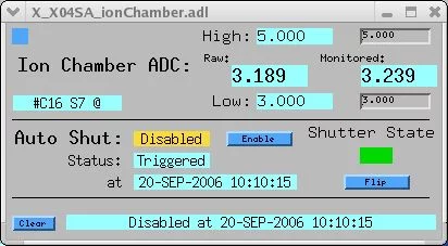
The mini-IO protection widget. The ion chamber monitor widget will close the fast photon shutter if the analog current reading exceeds the value given in the field "High" and the yellow field in Auto-Shut shows "enabled".
The widget is available under Top level launcher/in-situ surface diffractometer/ion chamber monitor. To establish what threshold should be entered into the "High" field, turn up the voltage of the ion chamber controller S-2341A in the main rack in EH3 to 300 V and set the current sensitivity to 10-8. Insert filters upstream (using the filter widget) to a transmission of 10-3. Then disable the "Auto Shut" feature on the widget, close the slow beam stop plate (and the detector slits, to be on the safe side), and slowly move step by step the diffractometer so that the detector arm moves into the direct beam. At GAM = DEL = 0 (assuming correctly adjusted motor values), note the raw or monitored ion chamber value in the widget. Enter half this value into the "High" field. Typical values appear to be about 0.5. Lastly, don't forget to enable the "Auto Shut" feature on the widget again.
Back to top
Operating methods
Using the PILATUS detector, we have been able to record CTRs and reflectivity curves with unsurpassed quality and speed. Typical procedures using this novel detector and recording geometry are described in an Acta Crystallographica A paper here and a more recent Journal of Applied Crystallography paper here.
Back to top
Back to top
Flatfield correction and trimfiles

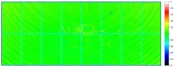
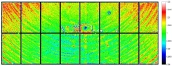
Flatfield correction images are recorded at the energy at which the experiments are being carried out. Typically, one places a scattering object in the beam, moves the detector to a position where the scatter is homogeneous and contains no Debye-Scherrer cones or diffraction spots, and records enough images so that the statistics are sufficient for the job at hand. An example of a flatfield image at 3 different intensity scale ranges is shown below
Flatfield image recorded at 16 keV. Click to enlarge each image. Note the three different intensity scales. The 16 different regions are evident from the less sensitive border pixels. Some minor damage is also noticeable.
Users can upload trimfiles into the detector control software, which act as high-pass filters for suppressing fluorescence signal. The response falloff has about a 500 eV width, and trimfiles exist for 6, 9, 12, and 16 keV.
A description of how to record flatfield and trim files can be found here.
Back to top
On-line image viewer OLIVA
A MATLAB program has been written, that allows one to view the most recently recorded pixel image. The program is called OLIVA. Here is a description of how to run OLIVA:
In a shell on PC6025, type in: cd /sls/X04SA/data/x04sa/sddir/software/matlab/ In this directory, call up MATLAB by typing in: matlab & In the MATLAB command shell, type in: oliva
In a shell on PC6025, type in: cd /sls/X04SA/data/x04sa/sddir/software/matlab/ In this directory, call up MATLAB by typing in: matlab & In the MATLAB command shell, type in: oliva
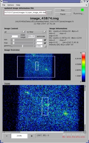
OLIVA on-line viewer panel
The program needs to know where to look for the most recent image to display. The field in the top-left hand corner of the OLIVA panel contains the "updated image information file". By clicking on the file navigator button (the grey box with 3 dots), navigate to and select:
whereby mysample_mydate is the name of your project that you created using the SPEC command sdStartup, an example of which might be ybco_20070610 (a beamtime on YBCO started on 10th June, 2007)
You can run/pause the program by clicking on the Run/Pause buttons at the top-right.
Back to top
/sls/X04SA/Data1/ES3/expdata/mysample_mydate/pixel/images/spec_image_info.dat
whereby mysample_mydate is the name of your project that you created using the SPEC command sdStartup, an example of which might be ybco_20070610 (a beamtime on YBCO started on 10th June, 2007)
You can run/pause the program by clicking on the Run/Pause buttons at the top-right.
Back to top
Pixel image MATLAB analysis
Atomic functions written in MATLAB, which can be applied for data analysis and extraction of images recorded using the pixel detector are available here. Chris Schlepuetz has written a sophisticated GUI in MATLAB for extracting data and creating CTR or SSR data files, which uses the scan logs created by SPEC at our beamline. A screenshot of the GUI can be found here. Anyone interested in using this program should contact Chris Schlepuetz or Phil Willmott
Back to top
Back to top
Troubleshooting
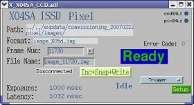
The pixel control widget panel. Click to enlarge.
- Control computer "NOT MASTER" If, when you try to record an image via SPEC (and you have chosen connect on the trigger pull-down menu), the pixel control widget shows a red panel containing the message "NOT MASTER" (this is normally blue and shows "Ready"), this unfortunately means you have to restart the pixel control program tvx on the computer PC5888 (via remote connection using PC6025)
- Widget freezing It can occur that the control computer PC5758 loses communication with the pixel computer. This is evident by the pixSNL dot at the top-right hand corner of the pixel control widget not continually hopping left and right (i.e., it indicates that communication is frozen). If this case, you must reboot the ES3 VME-crate. To do this, open a shell in PC5758 and type
-
rmc X04SA-VME-ES3 - This brings up a "remote minicom" shell (hence rmc), in which you then type
-
CTRL-x - which will begin the rebooting of the ES3 crate. This takes a minute or two to complete, during which, the fields for those EPICS channels on display which are connected to ES3 will go white. You can then exit the rmc, by typing
-
CTRL-a, then q - after which you should confirm you want to exit without resetting.