
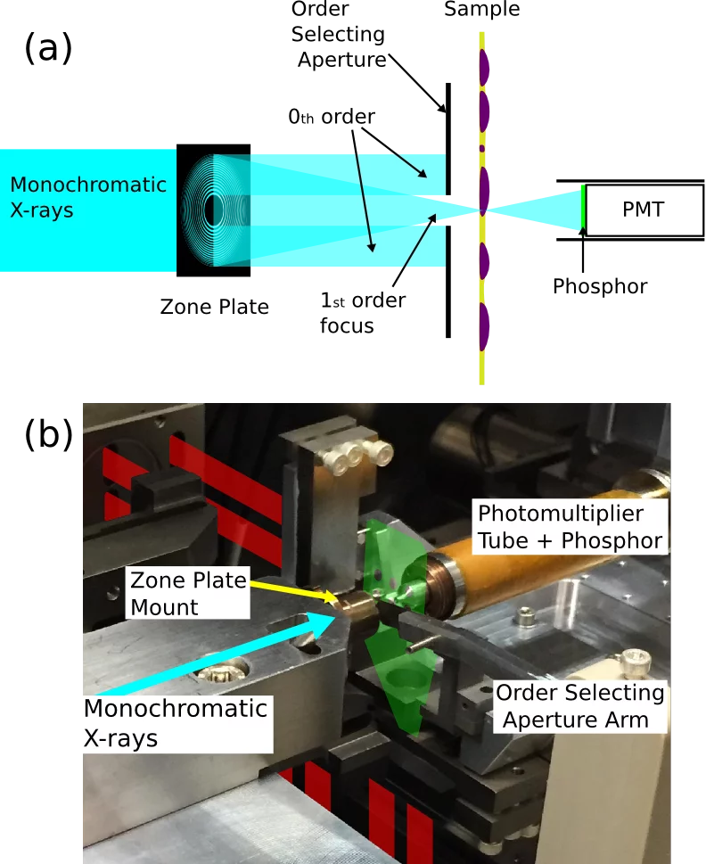
a)Schematic of the STXM technique. b) Photograph of the major components of the PolLux STXM. The position and shape of the plate on which samples are mounted is indicated in green, while the interferometer beams are indicated in red.
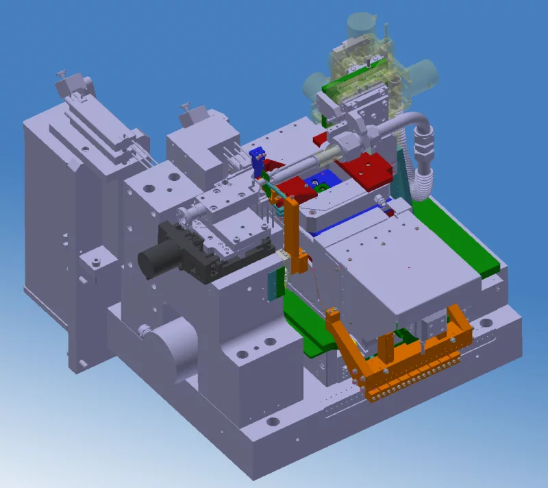
3D rendered model of the in-vacuum components of the PolLux STXM endstation.
PolLux has a scanning transmission X-ray microscope (STXM) endstation, which is capable of producing high resolution images (better than 50 nm) and soft X-ray absorption spectra of very small sample areas. By combining imaging and spectroscopy, PolLux can map out properties such as elemental and chemical composition, molecular orientation, oxidation states, magnetic domains as well as thickness variations with high resolution. Central to the operation of a STXM is a Fresnel zone plate that focuses a monochromatic X-ray beam through an aperture (which blocks the unfocused 0th order light and the higher focus orders) and onto a sample that is thin enough to be semi-transparent at the appropriate X-ray wavelength. A detector positioned behind the sample measures the transmitted photon flux. Scanning of the sample, combined with repeated transmission measurements, build up an image of the sample, while varying the energy of the X-ray beam allows measurement of spectra and alters the image contrast with respect to the spectroscopic properties of the sample components. An interferometer measures the relative position of the sample with respect to the zone plate (and thus its focus position) and ensures accuracy of the measured image pixel positions. The PolLux STXM is controlled by Pixelator.
Zone Plates
A number of zone plates are available for use at PolLux, providing various trade-offs between efficiency, focal length and resolution. As a rule of thumb, the resolution of the instrument is similar to the outermost zone width of the zone plate. Zone plates are dispersive optics and so the focal length will vary with photon energy. Note that the difference in zone plate resolution is only useful in high resolution images and that experiments not pushing the limits of the instrument are usually better off choosing a higher efficiency zone plate. Non-standard zone plates are only available at the discretion of the beamline staff.| Outermost Zone Width | Focal Length (μm/eV) | Manufacturer | Notes |
|---|---|---|---|
| 35 nm | 6.8 | CXRO | Longest focal length, best for environmental cells |
| 30 nm | 5.8 | LMN | Good efficiency |
| 25 nm | 4.8 | CXRO | Higher resolution |
| 25 nm | 4.8 | LMN | Higher resolution, made from Ni for improved performance at the C K-edge |
| 15 nm | 1.8 | LMN | Higher resolution. Restricted to photon energies above ~600 eV and with very short focal length. |
| 12.5 nm | 1.0 | LMN | Non-standard! Restricted to photon energies above ~1000 eV and with very short focal length. |
A set of zone plates are maintained free of carbon for use in imaging at the carbon K-edge.
Detectors
A number of different detector types are available for enabling different experiments. Non-standard detectors are only available at the discretion of the beamline staff.| Detector | Notes |
|---|---|
| Photomultiplier Tube (PMT) |
Photomultiplier tube with a phosphor screen.
Standard detector with high efficiency over a wide range of energies. Download drawings of the detector tip. |
| Silicon Avalanche Photodiode (APD) |
Silicon avalanche photodiode.
Narrower pulses enable time resolved imaging. |
| Fast Camera (CCD) |
View of the flight tube and CCD camera. Inset is a better view of the sample area with the phosphor screen and transfer optics.
A phosphor screen close to the sample, with transfer optics allow "differential phase contrast" type imaging with an out-of-vacuum fast CCD |
| Channeltron |
Channeltron detector.
Non-standard! Total electron yield (TEY) detection of sample surface can be performed simultaneously with transmission measurements with the PMT. Note that this detector requires very good vacuum and so is difficult to use. |


Sample Mounts
| Name | Notes |
|---|---|
| Open Mount |
sample mount that allows a lot of open space around it.
Sample mount plate that allows a lot of open space around it. Drawings of plate. |
| Open Tilted Mount |
Tilted open sample mount with sample plates mounted at (left) 30° yaw and (right) 30° pitch orientations.
Sample mount plates, and thus samples, can be mounted at 30° (fixed) in either yaw or pitch. Useful for circular magnetic dichroism measurements. |
| Tilted Mount |
Tilted sample mount with sample plates mounted at (left) 30° yaw, (centre) flat and (right) 30° pitch orientations.
Sample mount plates, and thus samples, can be mounted at 30° (fixed) in either yaw or pitch. Useful for circular magnetic dichroism measurements. |
| Heavy Mount |
High-stability sample mount with thick sample plates mounted at (left) 30° yaw and (right) flat orientations.
Stronger clamping and thicker sample mount plates for greater stability of samples involving greater weight and/or stiff connections (cables, tubes, etc). Download drawings of the standard sample mount plate and the high-stability mount plate. If you want to make something heavy, like an environmental cell, we recommend you to design it to fit the high-stability clamping mount or the "PCB mount" below. |
| PCB Mount |
High-stability sample mount for samples on PCB boards.
Screw mounting and for samples on PCB boards (or heavy environmental cells), allowing for robust electrical (or fluid) connections. Download PDF drawings |
| Azimuthal Rotation Stage |
Azimuthal rotation stage.
Computer controlled sample mount for adjusting the azimuthal position of the sample. Useful for linear dichroism experiments. |

 30° yaw and (right) 30° pitch orientations.")
 30° yaw, (centre) flat and (right) 30° pitch orientations.")
 30° yaw and (right) flat orientations.")


Miscelaneous Apparatus
| Name | Notes |
|---|---|
| Magnetic field |
A rotatable permanent magnet provides an out-of-plane field to a sample.
Variable magnetic fields up to 200 mT can be applied via a permanent magnet. The magnet can be rotated by a computer-controlled motor to different angles in order to vary the coupling into the pole pieces and hence vary the field at the sample. The field at the sample can be 0-200 mT in the out-of-plane configuration, or 0-100 mT for the in-plane configuration (in which the sample is tilted at 30° to the X-ray beam propagation for in-plane XMCD sensitivity). Note that the APD detector is not affected by magnetic fields (the PMT is affected by magnetic fields). |
| Heating & Cooling | Non-standard! Small heaters can be attached to the sample mount plates and cooling can be performed via a copper braid. A temperature range between about 100°C and -20°C is possible. |
| Optical Microscope |
Optical microscope with position encoders and attached camera and PC.
An optical microscope is available that can record images of samples (including observed positions) and enable easy location of areas of interest to image in the STXM. |
| Spin-coater Adapter |
A spin-coater adapter that makes it easy to use membranes on a spin-coaters vacuum-chuck.
Many users wish to spin-coat films onto membranes, but the membranes are not very compatible with the vacuum-chucks commonly found on spin-coaters. Therefore we designed this adapter to make it easy - you can download the design to make your own. |


Partners and Collaborators


