
Optical elements
The optical components of the X10DA beamline,their functions and there position from the source are listed here.
| Beamline compounent | Function | Distance from the source [m] |
|---|---|---|
| Graphite Filter | Beam attenuation | 5.970 |
| White beam slits | Definition of beam size | 6.364 |
| Collimating Mirror M1 | Vertical collimation | 7.744 |
| Double Crystal Monochromator (DCM) | Monochromatic beam | 11.850 |
| QEXAFS Monochromator | Fast scanning,Monochromatic beam | 12.980 |
| Bremsstrahlung stoper | Blocking white and pink beam | 13.635 |
| Monochromatic slits | Beam definition (blocking scattering beam) | 14.145 |
| Intensity monitor (BM2) | Monitoring the beam intensity | 14.525 |
| Toroidal Mirror M2 | Focusing the beam | 15.580 |
| 4 diodes BPM | Monitoring the beam shape, position and intensity | 17.276 |
| HRM | Rejection of high order harmonics | ~24.000 |
Mirrors
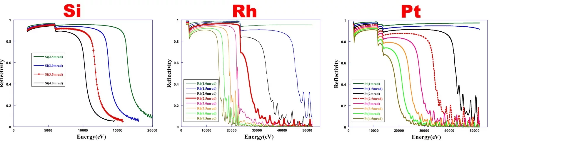
Two mirrors are used at the superXAS beamline a first vertically collimating mirror (M1) and Toroidal focusing mirror (M2)
The mirrors can be remotely adjusted in five independent degrees of freedom. and the rotations (pitch, roll and yaw) are realized by means of software pseudo motors. The two (02) UHV compatible translation stages installed in the vacuum chamber with a UHV compatible stepper motor for each stage allow horizontal translation of the mirror. Thus, coating can be changed between Pt and Rh (plus Si coating for M1).
Vertical translations are performed by means of vertical jacks that also perform the pitch and roll rotations.
Brief system overview
The high stability mirror system is designed to be very robust, reliable and to allow easy access for installation and maintenance. A very important design aspect of the mirrors systems is the complete mechanical separation between the optics and the vacuum chamber. This aims to avoid as much as possible vibrations propagation to the mirrors. A massive granite block directly supports the mirrors holders/benders that are mechanically isolated from the vacuum chamber by means edge-welded bellows.The mirrors can be remotely adjusted in five independent degrees of freedom. and the rotations (pitch, roll and yaw) are realized by means of software pseudo motors. The two (02) UHV compatible translation stages installed in the vacuum chamber with a UHV compatible stepper motor for each stage allow horizontal translation of the mirror. Thus, coating can be changed between Pt and Rh (plus Si coating for M1).
Vertical translations are performed by means of vertical jacks that also perform the pitch and roll rotations.
Mirror Substrates Specifications
| / | M1 | M2 |
|---|---|---|
| Mirror Substrate | Monocrystalline Silicon | Monocrystalline Silicon |
| Direction of Reflection | Upwards | Downwards |
| Shape | Flat, Cylindrically bent to tangential cylinder | sagittal cylinder cylindrically bent to torus |
| Tangential Bending Radius Range | 4.5 km - flat (>40 km) | 3 km - flat (>40 km) |
| Sagittal Bending Radius | flat | 20 mm (Pt Coated) and 30 mm (Rh coated) |
| Substrate length | Approx. 1100 mm | Approx. 1100 mm |
| Substrate width | Approx. 80 mm | Approx. 70 mm |
| Substrate thickness | > 40 mm | > 40 mm |
| Optical Active Surface: length | 1000 mm | 1000 mm |
| Optical Active Surface: width | 3 x 20 mm (Si,Rh & Pt) | 2 x 34 mm (Rh & Pt) |
| Slope Error: sagittal | < 10 µrad rms | < 20 µrad rms |
| Slope Error: tangential | < 1.5 µrad rms on 1000 mm | < 2.5 µrad rms on 1000 mm |
| Micro Roughness | < 3 Å rms | < 3 Å rms |
| Coating | Rh & Pt > 600 Å ; Cr underlayer Bare central Si stripe | Rh & Pt > 600 Å ; Cr underlayer |
| Cooling | max power load ~100 W - clamped side watercooling | NO |
Double Crystal Monochromator (DCM)
The optics of the DCM reflects the beam upwards (positive offset). The Goniometer turns counter-clockwise for positive Bragg angles (looking directly to the optics). Two sets of silicon crystals, Si (111) and Si(311), are accommodated inside the vessel at once and the crystal cut can be changed by an in-situ exchange of the crystal pair. The Si(111) allow to access lower enrgies (down to ~4.5 keV) and the Si(311) allows reaching the higher energies (up to ~35 keV).
Dimensions of the 1st crystal are 40x70x10 mm3 and the second crystal are 40 x 170 x 30 mm3 (width x length x thickness). The long 2nd crystal substitutes the necessity for a longitudinal translation of the crystal (Z axis) for a fixed-exit beam with respect to the 1st crystal. Exchanging between the diffracting, Si(111) and Si(311), crystals is done in-situ by a movement of the horizontal linear stage.
In order to withstand the thermal heat load the crystals are water cooled passively via a copper cooling device. Both crystals are mounted in parallel on a single cooling device.
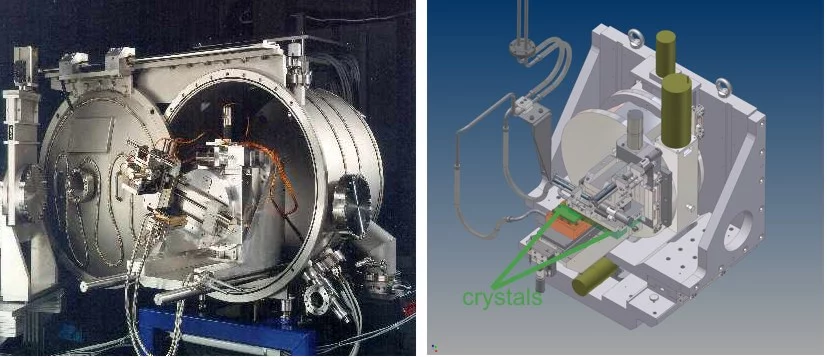
Quick Exafs Monochromator (QEXAFS)
The QEXAFS monochromator consists of an in vacuum goniometer for selecting a specific Bragg angle. A fast oscillating channel cut crystal is attached to this goniometer. This system facilitates scan speeds for a specific energy range with up to ~40 scans per second. The oscillation of the monochromator crystal is caused through an eccentric disk that is continuously rotated by a motor.
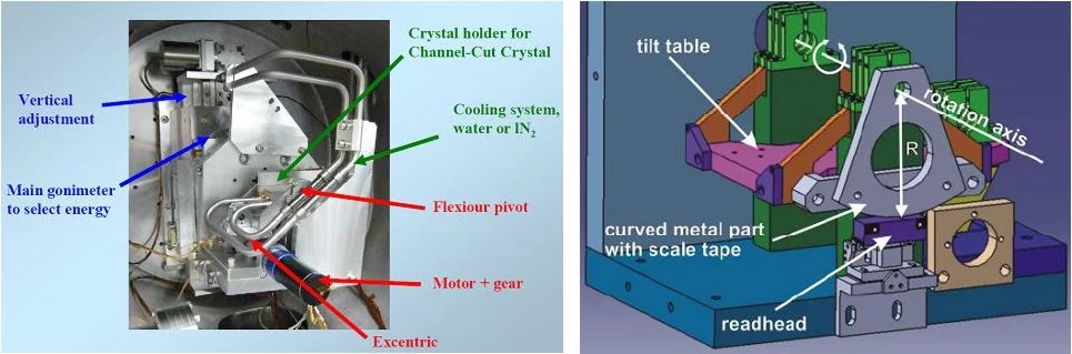
A set of disks with different eccentricities provides various angular ranges from 0.05 deg to 0.91 deg. About 40 Hz operation frequency is possible. Typical EXAFS scans then take 0.1 second and XANES scans of 12.5 ms are feasible.
The channel cut crystal is pre-aligned vertically using an accurately individually machined spacer in order to position the crystal surface onto the rotation axis of the goniometer in hight abd roll. The main goniometer angle varies between -3° (for adjustment) and 30° maximum. The final operational energy range depends on the crystal cut that is selected. Two sets of crystals, Si(111) and Si(311), are manually exchangeable during shutdown periods depending on the number and type of accepted proposals.
The channel cut crystal is pre-aligned vertically using an accurately individually machined spacer in order to position the crystal surface onto the rotation axis of the goniometer in hight abd roll. The main goniometer angle varies between -3° (for adjustment) and 30° maximum. The final operational energy range depends on the crystal cut that is selected. Two sets of crystals, Si(111) and Si(311), are manually exchangeable during shutdown periods depending on the number and type of accepted proposals.