Rationale: Real space, full-field imaging, and in particular tomography, needs a homogeneous and stable beam profile, in order to perform optimal background corrections.
Because of the high coherence of the radiation produced by third-generation synchrotron radiation facilities like the SLS, all the optical components (windows, mirrors and monochromator) must be designed with particular care in order to avoid deterioration of the beam profile.
The design criteria for the optics of the TOMCAT beamline have been:
- Simplify the optics (i.e., minimize the number of optical elements)
- Optimize optics for bandwidth rather than for energy resolution
- Make monochromatic beam and white beam available
- Energy range: 8-45 keV
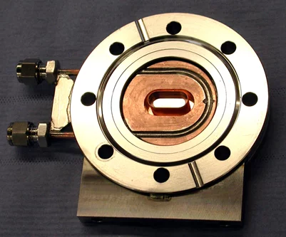
CVD diamond window support, with cooling pipes
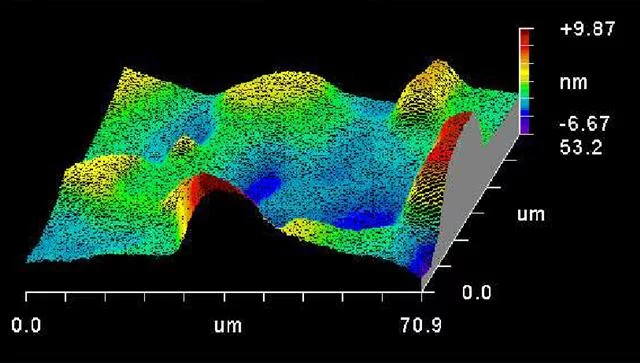
Roughness measurement of the diamond thin film
Optics The main optical component of the TOMCAT beamline is a fixed-exit double crystal multilayer monochromator (DCMM) which covers an energy range from 8 to 45 keV. Design and manufacturing have been done by CINEL Strumenti Scientifici from Italy. The DCMM is located in the front-end, at approximately 7 m from the source: this allows it to accept a large angular divergence while keeping the optical elements very compact. [Ru/C]100 and a [W/Si]100 multilayer stripes have been coated 8 mm apart from each other on a Si111 substrate (active area of 150x50 mm2). As a result, the energy bandwidth of the DCMM is a few percent when multilayer are used or 10-4 when the silicon is used. The slope errors in the direction along and across the optic are better than 0.5 μrad RMS and 5 μrad RMS respectively. Surface roughness is less than 0.3 nm RMS. When operating with multilayers the Bragg angle varies between θ = 1.82° and θ = 0.265° for energies ranging from 5 keV up to 45 keV. For the low-energy settings, the power density is 80 mW/mm2 and is dissipated via water cooling. The crystal optics are mounted on two independent high-precision goniometers. The first crystal has motorized pitch, roll, and horizontal translation (for stripes selection); the second crystal has the same degrees of freedom and, in addition, yaw and vertical translation. The whole system is positioned on a base plate that can be vertically adjusted. The distance between both crystals can be increased up to 850 mm. Instead of using a collimating mirror, the vertical size of the beam is controlled by moving the endstation along the beam path (up to 15 m travel range).
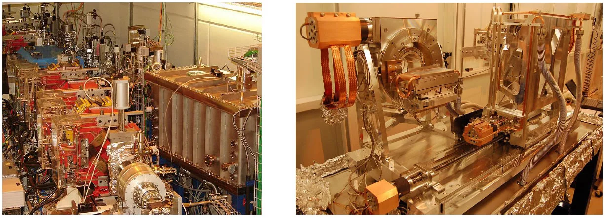
Left: View of the sector 2 of the SLS tunnel: visible are the magnets of the storage ring (in the foreground) as well as the TOMCAT front end (background). The monochromator vacuum chamber is clearly visible on the right side.
Right: View of the mechanics of the mono: the multilayer crystals are mounted on two separate goniometer towers. The first crystal can be adjusted in transverse direction as well as in pitch and roll. The second crystal has transverse, longitudinal (up to 850 mm range), vertical as well as pitch, roll and yaw adjustments. Both crystals are supported by a bank which is vertically translated and tilted by three jacks.
Right: View of the mechanics of the mono: the multilayer crystals are mounted on two separate goniometer towers. The first crystal can be adjusted in transverse direction as well as in pitch and roll. The second crystal has transverse, longitudinal (up to 850 mm range), vertical as well as pitch, roll and yaw adjustments. Both crystals are supported by a bank which is vertically translated and tilted by three jacks.
Monochromatic Operation: The expected multilayer/crystal translations are shown below. The beam offset will be between 7 and 10 mm for multilayers and 25 mm for the Si111.
| Energy Range | 8-45 keV |
|---|---|
| Energy bandwidth | 2-3 % with multilayers 0.018% with Si111 |
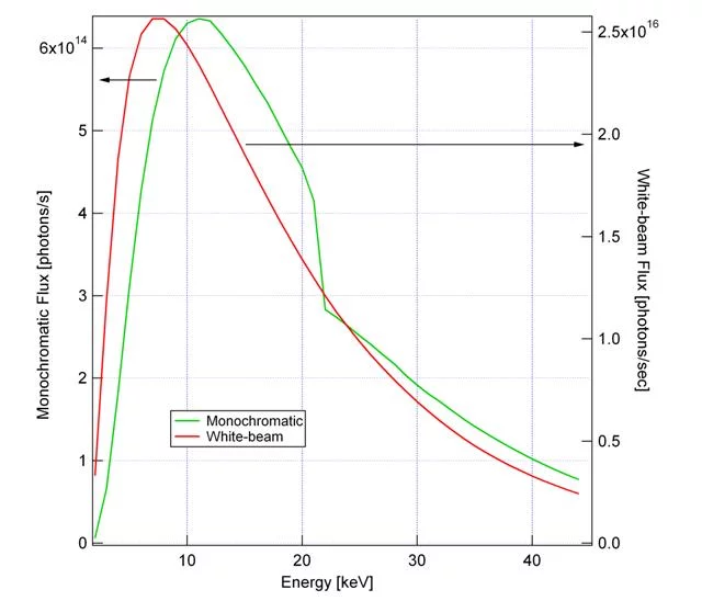
| Photon Flux (ph/s) with multilayers | > 5e14 @ 10 keV > 3e14 @ 20 keV > 1e14 @ 40 keV |
| Beam Size @ 20 m from source | 40 mm (H) x 4-7 mm (V) for energies between 10-30 keV |
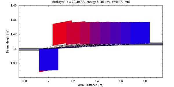
Expected translation of the second crystal along the beam path when multilayers are used. (Click to enlarge)
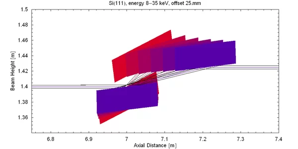
Expected translation of the second crystal along the beam path when Si111 crystal is used. (Click to enlarge)
White beam operation: The DCMM can be easily removed from the beam path and white beam radiation can be provided at the endstation. Filter batteries (Four quadruple and one triple) are available to pre-condition the radiation.
| Beam Size @ 20 m from source | 40 mm (H) x 9 mm (V) |
|---|---|
| Filter Battery 0 | 5 mm pyrolitic graphite, 20 mm pyrolitic graphite, 20 mm pyrolitic graphite + 75 μm Pd |
| Filter Battery 1 | 100 μm, 200 μm, 400 μm Al, 20 μm Cu |
| Filter Battery 2 | 50 μm Al, 10 μm, 40 μm, 50 μm Al |
| Filter Battery 3 | 10 μm , 50 μm Fe, 10 μm Cu, 100 μm Al |
| Filter Battery 4 | 10 μm Cu, 100 μm Al, 200 μm Al |
The expected performance of the multilayer monochromator (bandwidth between 2-3 %) is depicted in the graph below.