
Endstation 1
Standard configuration for absorption-based and edge-enhanced radiography and tomography
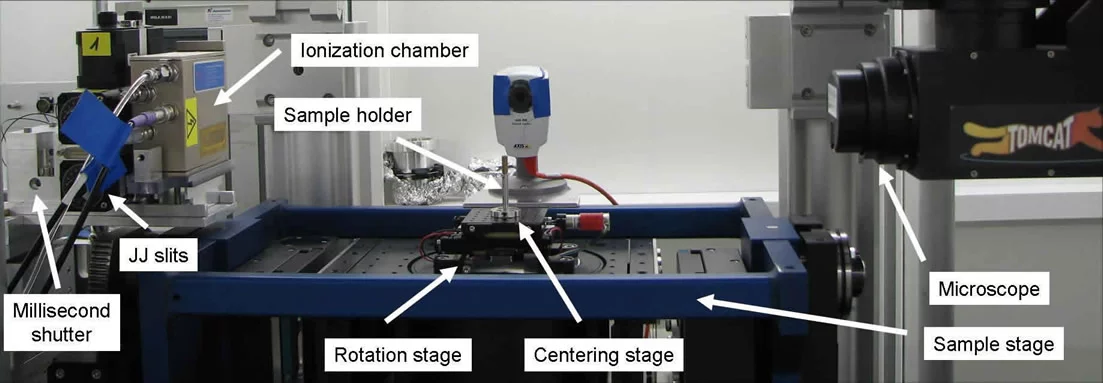
The TOMCAT endstation for tomographic microscopy allows for sample translation along the three spatial directions with a resolution better than 1μm. The axis perpendicular to the beam direction has a reproducibility of 0.1μm; this is imperative for an artifact-free acquisition of reference images. The sample can also be centered within 0.1μm reproducibility.
The rotation axis is a custom-modified, Aerotech air-bearing-based system (link) and has a run-time error of less then 1μm at 100 mm from the rotation surface. It rotates with speeds up to 10Hz (3600deg/s). A slip ring system for electrical contacts is available to transmit electrical signals or inputs through the rotation stage.
The standard setup is very simple and straigh-forward to use. The system is fairly flexible and capable of accommodating a variety of user-specific environments and sample setups. Please contact the beamline staff if you require a non-standard configuration for your experiments.
Additional details on sample mounting and sample environment can be found here.
High-speed tomography for time-resolved dynamic studies (4D)
Building on the same high-precision infrastructure as the standard tomography setup described above, TOMCAT offers world-leading capabilities for a continuous, ultra-fast acquisition of tomographic datasets. The dynamic evolution of samples under in situ, operando, or in vivo conditions can be investigated by measuring a rapid series of 3D volume data sets as a function of time (4D dataset). Individual 3D volume data sets consisting of hundreds to thousands of radiographic projections can be measured in typically well under one second, and thanks to the in-house development of the GigaFRoST high-speed camera and readout system, the total duration of data acquisition is no longer limited by the on-board camera memory. Data are streamed directly to a data acquisition server providing a high data throughput of nearly 8 GB/s, real-time preview capabilities, as well as sophisticated protocols for triggering, gating, and selective storage of data.
The high-speed setup is compatible with the usual absorption and single distance propagation-based phase contrast tomography modalities. In practice, phase contrast is almost always the contrast mechanism of choice since it yields much better contrast for the typically very noisy and low intensity data acquired at high frame rates. Data can be acquired either using the high bandwidth monochromatic beam from the multilayer monochromator, or using a filtered white beam providing even more flux and, in particular, a significant flux increase at higher energies. The GigaFRoST camera is, in principle, compatible with all of the TOMCAT microscope choices (see the section on Detectors), though in practice the white beam microscopes are used much more often than those for monochromatic beam. Naturally, the necessary acquisition time increases when choosing smaller pixel sizes.
Typical detector frame rates for the fast measurements range from 1 kHz at full frame to up to 20 kHz using a reduced region of interest (ROI) on the detector. The achievable frame rates and the associated maximum number of frames that fit into the server memory (512 GB) and the total acquisition time compared to the commercially available pco.Dimax camera are listed in the following table:
| ROI size(hxv) | Max. frame rate | #frames pco.Dimax (36 GB RAM) |
#frames GigaFRoST (512 GB RAM) |
|---|---|---|---|
| Total recording time | 5 sec | 57.3 sec | |
| 2016 x 2016 | 1’255 | 6’307 | 71’860 |
| 2016 x 1008 | 2’490 | ~12’614 | 143’720 |
| 1920 x 1080 | 2’424 | 12’362 | 140’844 |
| 1008 x 1008 | 4’305 | 25’037 | 287’440 |
| 672 x 540 | 10’288 | ~ 70’100 | 804’832 |
| 480 x 288 | 21’907 | ~185’430 | 2’112’684 |
| 240 x 240 | 33’875 | ~445’036 | 2’621’440 |
For an in-depth description of the GigaFRoST camera system refer to R. Mokso, C. M. Schlepütz, G. Theidel, H. Billich, E. Schmid, T. Celcer, et al., "GigaFRoST: The Gigabit Fast Readout System for Tomography", J. Synchrotron Rad., 24 (6), 1250-1259 (2017). DOI: 10.1107/S1600577517013522.
Endstation 1 can accommodate various user-built sample environments (for example, compression or tensile rigs, heating or cooling stages, electrochemical sample cells, etc.) as well as the TOMCAT laser furnace for high temperature studies. Please contact beamline staff to discuss your experimental ideas and requirements in detail.
More technical information about the end station capabilities for time-resolved tomography can be found in the following article: G. Lovrić, R. Mokso, C. M. Schlepütz, and M. Stampanoni, "A multi-purpose imaging endstation for high-resolution micrometer-scaled sub-second tomography", Physica Medica, 32, 1771 (2016). DOI: 10.1016/j.ejmp.2016.08.012
Laser Setup for Elevated Temperature in situ Tomographic Microscopy
The TOMCAT beamline offers a laser-based heating system for time-resolved in situ imaging. The system incorporates two 150W lasers at 980nm wavelength that are positioned approximately 180° apart. Two sets of laser heads, with different spot sizes (1 x 0.2 mm2 or 4 x 6 mm2 (h x v)) are available. The lasers are manipulated by x, y, and z linear stages such that a user-specified position can be heated. The lasers are also capable of moving as the sample moves. Temperatures are measured either with a pyrometer (non-contact infra-red (IR) temperature measuring device), accessing a temperature range of 350-1800°C or a thermocouple for temperatures from room temperature to 1200°C. Power to the lasers is dynamically controlled based on the temperature read-out from the pyrometer/thermocouple, and temperature profiles are determined based on user specifications. The current setup is capable of both near-isothermal and directional heating within these temperature ranges. The laser system is compatible with various beamline configurations and can be used in multiple imaging modalities. If an atmosphere different from air is required, a gas cover solution is available. Users are responsible for providing sample holders and setups that are compatible with the layout of the laser system. Please contact beamline staff well in advance if you would like to use this system such that we can optimally assist you in planning your experiments.
For further information, please see: J.L. Fife, M. Rappaz, M. Pistone, T. Celcer, G. Mikuljan, and M. Stampanoni. "Development of a laser-based heating system for in-situ synchrotron-based x-ray tomograpic microscopy", J. Synch. Rad. 19, 352-358, (2012). DOI: 10.1107/S0909049512003287
Endstation 2
Differential Phase Contrast (DPC) Imaging
The second TOMCAT endstation offers phase contrast imaging based on grating interferometry (see T. Weitkamp, A. Diaz, C. David, F. Pfeiffer, M. Stampanoni, P. Cloetens, E. Ziegler X-ray phase imaging with a grating interferometer, Opt. Express 13, 6296-6304 (2005), pdf). The plug-in for DPC imaging can be easily mounted on the standard setup at TOMCAT. The figure below shows the interferometer mounted on the beamline.

Experimental setup for Differential Phase Contrast at TOMCAT. The nanometer-precise periodic phase stepping is obtained by using a PSI in-house developed nanoconverter. For more details see S. Henein, M. Stampanoni, U. Frommherz, M. Riina, 'The Nanoconverter: a novel flexure-based mechanism to convert microns into nanometers', Proceedings of the 7th euspen International Conference – Bremen - May 2007, PDF-file.
|

The beam splitter grating (G1 – pitch 4 mm) splits the incident beam into essentially two first diffraction orders, which form a periodic pattern in the plane of the analyzer grating (G2 – pitch 2 mm). A phase object in the incident beam will cause slight refraction and therefore modifications of the original wave-front profile. These variations result in changes of the locally transmitted intensity through the analyser. This detected signal contains quantitative information on the phase gradient of the object. To separate this phase information from other contributions, a phase-stepping approach is used (T. Weitkamp, A. Diaz, C. David, F. Pfeiffer, M. Stampanoni, P. Cloetens, E. Ziegler, X-ray phase imaging with a grating interferometer, Opt. Express 13, 6296-6304 (2005), PDF-file).
|
Nanoscope
Linking micrometer and nanometer scales, the TOMCAT nanoscope was commissioned in 2009. Based on Zernike phase contrast, this full-field microscope is composed of:
- a condenser: a custom designed beamshaper producing a top-flat illumination in the focal plane
- a series of Fresnel Zone Plates (FZP) objectives, with different diameters on the same frame (to be selected according to the working energy)
- phase dots (optional) placed at the back-focal distance of the FZP to generate Zernike phase contrast.
The detector, placed downstream about 10 m, records the magnified phase contrast image of the sample. The field-of-view is from about 75um2.
Thanks to the latest improvements in optical design, specifically with regards to the beamshaper and the Fresnel Zone Plate, as well as on the hardware of the setup itself to produce higher stability, we are now able to use the nanoscope from 8 keV to 20 keV in multilayer or Silicon Monochromatique mode, leading to a pixel size down to 65nm (approximately 150/200 nm spatial resolution). The setup can be used in absorption or phase contrast mode for a wide range of applications, including biology, geology, materials science, and paleontology.
For further information, please see: