
Integral experiments aimed at validating data sets and calculation methods for the design of fast breeder reactors cooled with gas
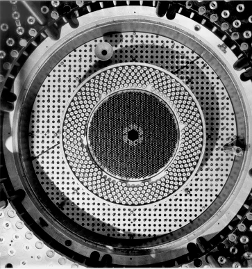
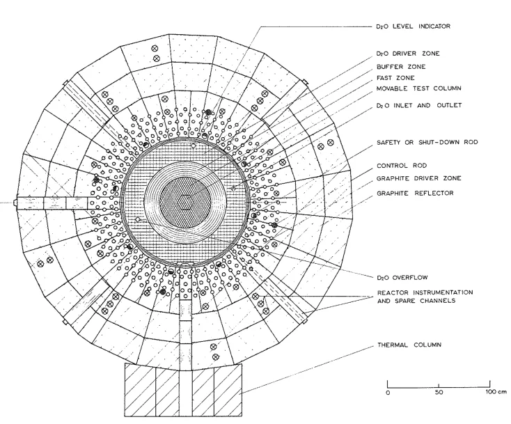
Top view of GCFR core
Integral experiments aimed at validating data sets and calculation methods for the design of fast breeder reactors cooled with gas.
Research and development work for fast breeder reactor in Switzerland began in 1967 following the cancellation of the earlier Swiss reactor system based on heavy water moderator and CO2 coolant. Switzerland decided to concentrate on the gas-cooled fast reactor (GCFR) because of its previous experience.
Among the activities at the time, a programme was designed for measuring the neutron physics properties of fast reactor lattices in the PROTEUS facility. The programme spanned from April 1972 to April 1979 and aimed at providing integral experiments to validate codes and nuclear data. A total of 16 core configurations were studied to investigate the physics of PuO2/UO2 lattices cooled with gas but also heterogeneities in the loading of future power reactors, the reactivity effect of steam entry, the integral cross-sections of structural material and material used for shielding, and lastly thorium-bearing reactor systems.
The use of thorium in fast reactor to breed U-233 presented some challenges especially due to the limited knowledge of the nuclear data associated with Th-232. The last six core configurations of the programme were dedicated to the study of thorium in oxide and metal form, that was distributed homogeneously or as axial and radial blanket.
As of 2012, part of the experimental results obtained in the thorium phases of the GCFR programme have already shown to be useful measurements to improve recent evaluations (ENDF/B-VII, JEFF-3.1, JENDL-4.0) of thorium and other isotope cross-sections in the fast domain [1]. We think that further re-analyses of the GCFR experimental results with modern calculation tools and nuclear data libraries could continue, in the context of GEN-IV, to help validating codes and nuclear data today.
The general layout of the core and a summary of the core configurations is presented below. The measurements techniques used and perfected during the programme follow.
Reactor Layout and Core Configurations
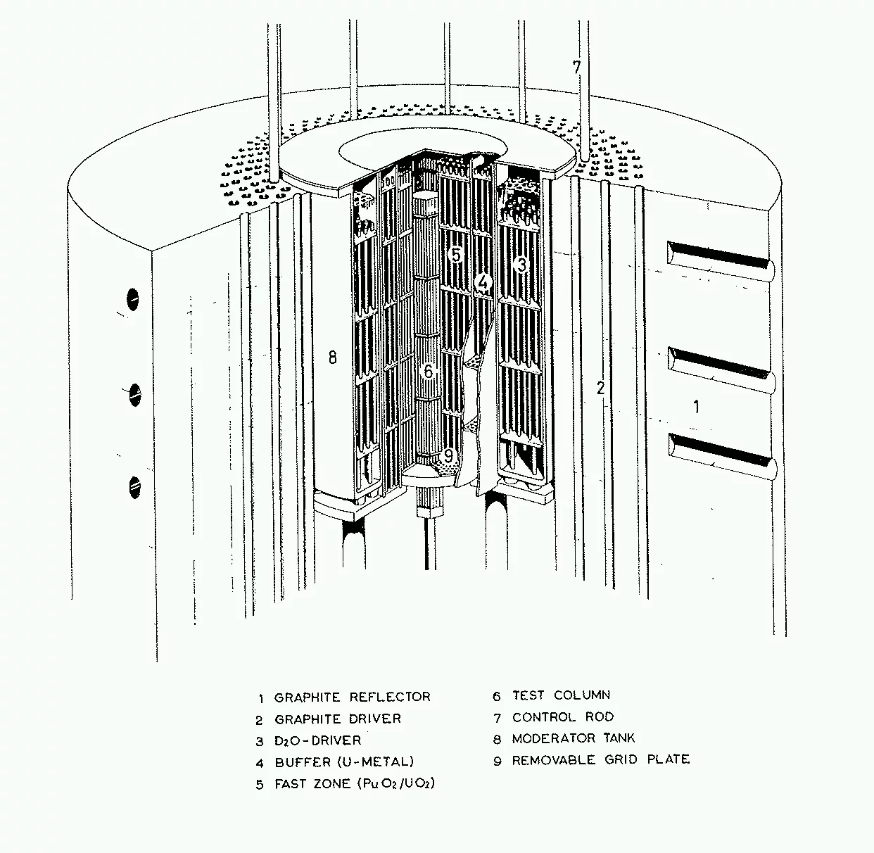
The GCFR programme took advantage of the driven nature of PROTEUS to minimise the amount of plutonium necessary to study fast breeder reactors. Inside the graphite driver region, the central cavity was filled with a D2O zone fuelled with 5 wt% UO2 fuel pins, a buffer region containing metallic natural uranium rods in air (starting from Core #3) and a central test zone filled with a GCFR-representative fuel lattice.
The reference configuration featured in the central test zone a regular hexagonal lattice (1 cm pitch) of about 2000 PuO2/UO2 fuel rods. The fuel contained 15 wt% plutonium, of which ~80% was fissile, and was clad in stainless steel. The fuel pellets had a diameter of 6.7 mm and a density of 10.6 g/cm3 and provided an active length of ~0.83 m sandwiched between a top and a bottom blanket of depleted uranium (0.42 wt% U-235, 10.5 g/cm3) to make up a total fuel length of 1.4 m.
The reference configuration featured in the central test zone a regular hexagonal lattice (1 cm pitch) of about 2000 PuO2/UO2 fuel rods. The fuel contained 15 wt% plutonium, of which ~80% was fissile, and was clad in stainless steel. The fuel pellets had a diameter of 6.7 mm and a density of 10.6 g/cm3 and provided an active length of ~0.83 m sandwiched between a top and a bottom blanket of depleted uranium (0.42 wt% U-235, 10.5 g/cm3) to make up a total fuel length of 1.4 m.
In the first part of the measurement campaign, the reference PuO2/UO2 core configuration was altered to simulate steam/water entry, effects of a sub-assembly stainless steel wall, B4C control rods and radial depleted uranium blankets. A large steel reflector (0.6 m thick) was also added on top of the central zone to benchmark iron cross-section data. The second part of the campaign was dedicated to the study of thorium nuclear data in a GCFR spectrum. For this purpose, the reference PuO2/UO2 test zone was modified to include, in turn, ThO2 and thorium metal fuel rods, distributed either quasi-homogeneously in the lattice, or introduced in the form of radial and axial blanket zones. The main core configurations and their specificities are detailed below.
| Core | Main Objective | Radial Layout | Axial Layout |
|---|---|---|---|
| 1 | Reference | PuO2/UO2 lattice | Depleted U top/bottom |
| 2 | Stainless steel | 2/3 PuO2/UO2 pins 1/3 stainless steel rods |
Depleted U top/bottom |
| 3 & 5 | Reference | PuO2/UO2 lattice | Depleted U top/bottom |
| 4 | Power Reactor Hete. | PuO2/UO2 lattice Central depleted UO2 column Steel wall of sub-assembly B4C control absorber |
Depleted U top/bottom |
| 4.a | Steam Entry | PuO2/UO2 lattice with polypropylene discs | Depleted U top/bottom |
| 6-8 & 10 | Structural Material Capture | PuO2/UO2 rods mixed with different number of steel rods | Depleted U top/bottom |
| 9 | Shielding | PuO2/UO2 lattice | Depleted U top/bottom and iron or steel upper shields |
| 11 | Repeat of Config. 3 | PuO2/UO2 lattice | Depleted U top/bottom |
| 12 | ThO2 homogeneous | ThO2-PuO2/UO2 lattice | Depleted U top/bottom |
| 13 | ThO2 radially heter. | ThO2 central blanket in PuO2/UO2 lattice | Depleted U top/bottom |
| 14 | ThO2 axially heter. | PuO2/UO2 lattice | Bottom depleted U blanket, top ThO2 blanket |
| 15 | Th metal radially heter. | Th metal central blanket in PuO2/UO2 lattice | Depleted U top/bottom |
| 16 | Th metal axially heter. | PuO2/UO2 lattice | Bottom depleted U blanket, top Th metal blanket |
| In configurations 1 and 2, the buffer was made of UO2 rods instead of U metal rods. | |||
Measurement techniques
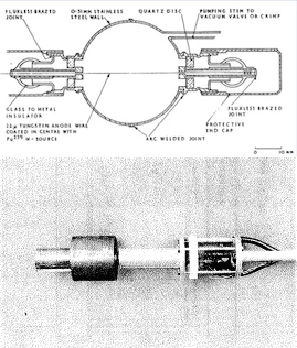
Schematics and picture of a proton recoil detector used for the neutron spectrum measurements.
Several types of measurements to determine reaction rate distributions, spectral indices, neutron spectrum or reactivity effects were made in each core configuration.
Neutron spectrum was measured mainly with proton recoil detectors, i.e. hydrogen-filled proportional counters. Several detectors with different hydrogen pressure (1 to 10 atm.) and several mixtures of hydrogen and argon were used. Unfolding of the proton energy spectrum measured in these detectors allowed to determine the neutron spectra between 20keV and 2.3MeV.
Spectral indices, i.e. reaction rate ratios, were mainly measured by activating foils inserted in between fuel pellets. A large number of foils with different deposits allowed to investigate the following spectral indices: C8/F9, F8, F9, F5/F9, C2/F9, F2/F9, F3/F9, (n,2n)2/C2, C7/F9 and F7/F9, where F and C stands for fission and capture and 2, 3, 5, 8 and 9 for Th-232, U-233, U-235, U-238 and Pu-239, respectively.
Spectral indices were measured mainly at the centre of the test zone lattice in order to beneficiate from the conditions most representative of infinite lattices. However, foils were also measured in several axial and radial positions in the core in order to determine reaction rate profiles, especially at the boundary between core and axial or radial blankets.
Measurements of U-235, U-233, Pu-239 and Th-232 fissions are based on measuring the gamma-ray emitted during the decay of the fission products. For the U-238 and Th-232 captures the 277.6keV and 312keV from decays of Np-239 and Pa-233 are measured. The 25.6keV gamma-ray line produced by the decay of Th-231 is measured to determine the amount of (n,2n) reactions in Th-232 foils. For this very low energy special attention has been paid to the self-absorption effects by using Th-232 foils with different thicknesses. The gamma-ray lines were measured with Hyper Pure Germanium detectors. Because the isotopic content of all foils was not know in all cases some foil measurements were scaled with absolutely calibrated fission chamber measurements performed at an alternate position in the core and/or in a thermal column.