

The following facilities are operated by the Experimental Thermal-Hydraulics group:
PANDA
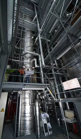
PANDA is a large-scale, thermal-hydraulics test facility designed and used for investigating containment system behavior and related phenomena for different ALWR designs, and for large-scale separate effect tests. The facility was used to study the passive decay heat removal systems and containment response of the Simplified Boiling Water Reactor (SBWR) and the Economic Simplified Boiling Water Reactor (ESBWR) designs from General Electric (GE), as well as of the SWR1000 design from Siemens-KWU (now KERENA design from AREVA) in the case of accident transients. Other studies were carried out on natural-circulation flow and stability in the Reactor Pressure Vessel (RPV) of advanced BWRs. The PANDA facility has a modular structure, consisting of six cylindrical pressure vessels and four water pools containing four condensers. In the studies related to the ESBWR, the vessels were representing: the Reactor Pressure Vessel, RPV (one vessel), the Drywell, DW (two vessels), the Suppression Chamber, SC (two vessels) and the Gravity Driven Cooling System, GDCS (one vessel). The pools and condensers represented the three Passive Containment Cooling Condensers (PCCs) and the Isolation Condenser (IC). The total volume of the six vessels is about 460 m3 , and the total height of the facility is 25 m. The maximum operating conditions are 10 bar pressure and 200°C. In the RPV, electrical heaters are installed with a maximum power of 1.5 MW, providing the steam injected into the vessels. The facility is equipped with auxiliary systems which allow injection into the vessels of air, steam, helium and water. These systems are regularly used to precondition the facility to the specified test conditions. The control system allows all the main operations needed for preconditioning the facility and for performing a test from a control room. The PANDA instrumentation allows for the measurement of fluid and wall temperatures, absolute and differential pressures, flow rates, heater power, gas concentrations and flow velocities with PIV systems. The sensors are implemented in all the compartments of the facility, in the system lines, and in the auxiliary systems. Experimental investigations carried on in the PANDA facility have been embedded in international projects, most of which under the auspices of the EU and OECD and with the support of a large number of Organizations (Regulatory Bodies, Technical Support Organizations, National Laboratories, Universities, Electric Utilities, Industries) worldwide.
LINX
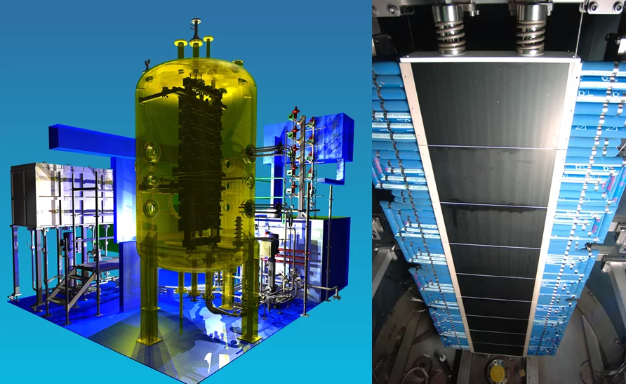
The LINX (Large scale Investigation of Natural circulation and miXing) facility is a medium scale thermal-hydraulic experimental facility that was originally designed for containment safety study, in particular passive safety systems based on natural circulation, mixing and condensation in presence of non-condensable gases. The LINX facility consists of a 9.42 m3 pressure vessel, a heat exchanger (heater/cooler) and various lines used for water and/or gas injection. The facility design pressure and temperature are 10 bar and 250°C, respectively. The facility is instrumented with more than 200 thermocouples, 40 sampling lines for gas concentration measurements. LINX has 12 glass windows which allow flow observation from outside, as well as the use of non-intrusive techniques such as photography and PIV, and Infrared measurement techniques. Optical probes, electromagnetic probes and Pitot tubes have also been implemented for some projects. In addition, a state-of-the-art control system allows for reliable and safe operation of the facility. The LINX facility has been part of many international projects devoted to containment safety, most of which are under European Framework Programs. Currently, LINX is used within a PhD program for the characterization of liquid film dynamics under condensation and re-evaporation conditions in cooperation with ENSI and IRSN. In the rendering is shown the newly implemented components in LINX (left): the cooling loop system outside the vessel and the cooling plates set up inside the vessel. Picture features temperature controlled plates (TCP) in the Vessel (right).
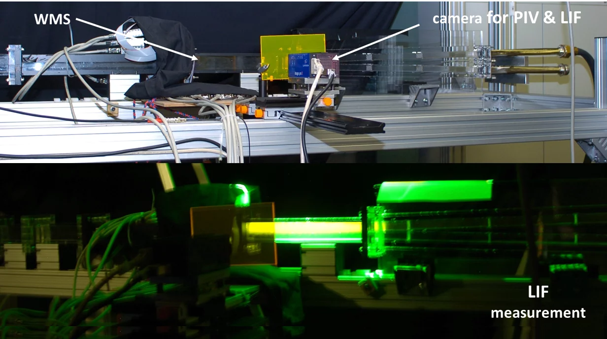
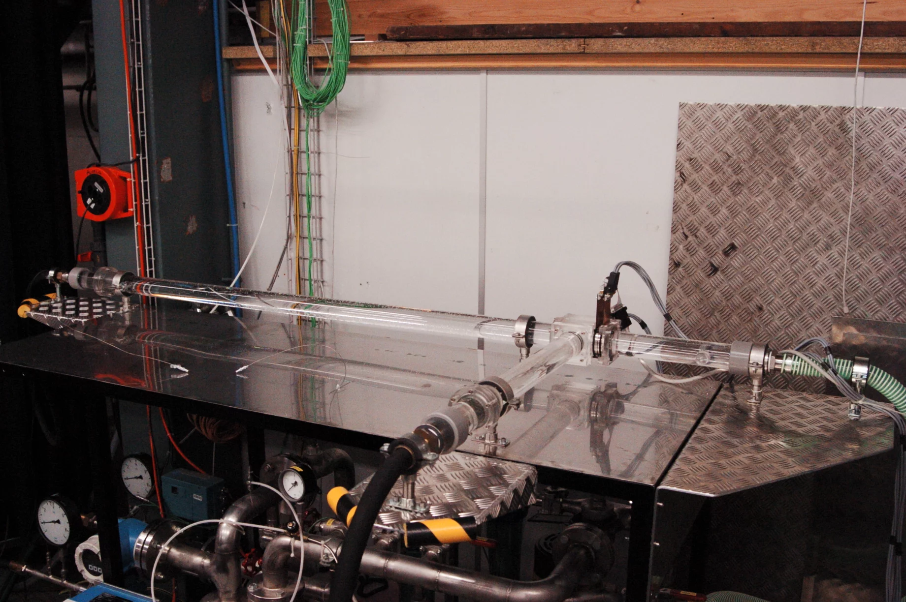
HOMER/GAMILO
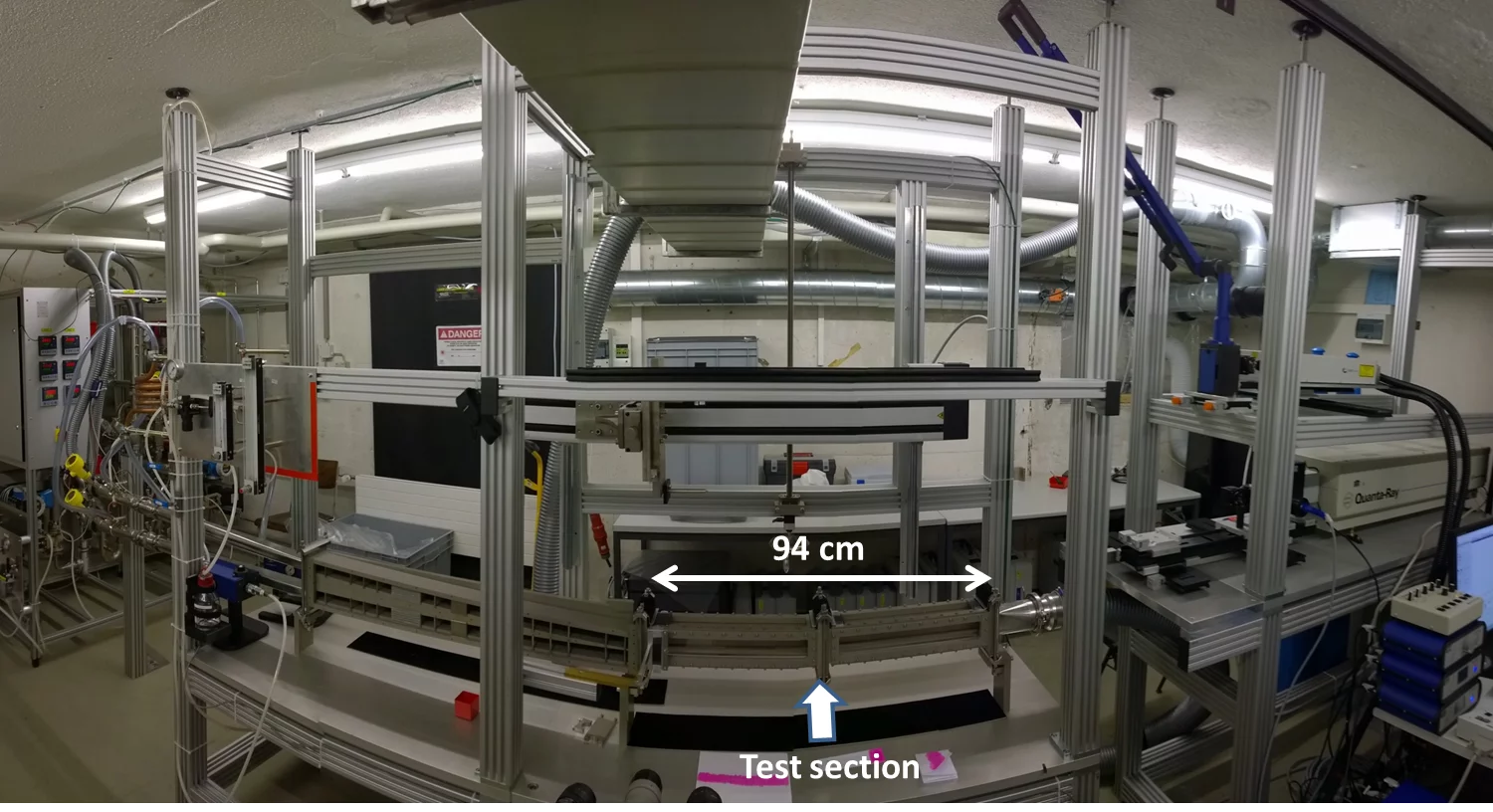
Shear layer and wake flows are examples of so called ‘building block’ flows for hydrodynamics which have been studied for a long time. The HOMER test facility (HOrizontal Mixing Experiment in a Rectangular channel) is dedicated to study such fundamental mixing processes in the presence of different density stratifications and shear strengths. The HOMER facility consists of a horizontal mixing section fed by two vertically stacked initially separated gas streams which interact downstream of a splitter plate. The strength of the density stratification can be controlled by changing the gas species in each of the streams. The streams may consist of pure nitrogen, pure helium, or a premixed mixture of both in one of the streams to adjust the density with respect to the nitrogen stream. In order to adjust the shear strength from isokinetic conditions - which results in a wake flow behind the splitter plate - to shear flow, independent velocity control of each stream was applied through GAMILO (an open GAs MIxing LOop) and experiments can be conducted at different bulk velocities in order to observe any Reynolds number effects on the developing flow fields. The tip of the splitter plate and the subsequent mixing zone formed downstream are located in a measurement section in which Particle-Image-Velocimetry (PIV) and Laser-Induced-Fluorescence (LIF) are applied.
AROBE
The Laboratory for Thermalhydraulics develops high-resolution measurement techniques for nuclear fuel bundle investigations. Neutron imaging, in general, is a useful, non-intrusive technique for visualizing low-Z materials (such as water or plastics) obscured by high-Z materials. This is the typical setting for the two-phase flow in rod bundle models (AROBE: Adiabatic ROd Bundle Experiments). We have successfully established this technique using the cold-neutron imaging beam line ICON of the SINQ facility at PSI (http://www.psi.ch/sinq/icon/) for liquid film thickness measurement in annular flows based on adiabatic air-water experiments in different, partial fuel bundle model geometries. Also the basic influence of prototypical spacers on the film thickness in annular flow has been tested in these experiments.
CNHT
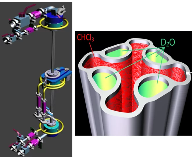
As an extension of the adiabatic fuel bundle tests, a PhD project is currently running to build and study a heated fuel bundle model (CNHT facility) by cold-neutron imaging. The facility features one undisturbed subchannel and the four neighboring fuel pins. The pins are heated by heavy water to decrease parasitic absorption of the neutrons in them. Chloroform (CHCl3) is used as a working fluid to enable studying convective boiling experiments and dry out at limited heating power and at low pressures. The high-resolution data (2-300um) provides novel insight into the flow behavior at the dry out which is otherwise difficult to access from a technical point of view. It also enables to examine the influence of different spacer types on the dry out limit contributing to the optimization of nuclear fuel bundle design and the validation of sub channel codes. A unique feature of the facility is the operation in sustained dry out mode.
TWOFAST
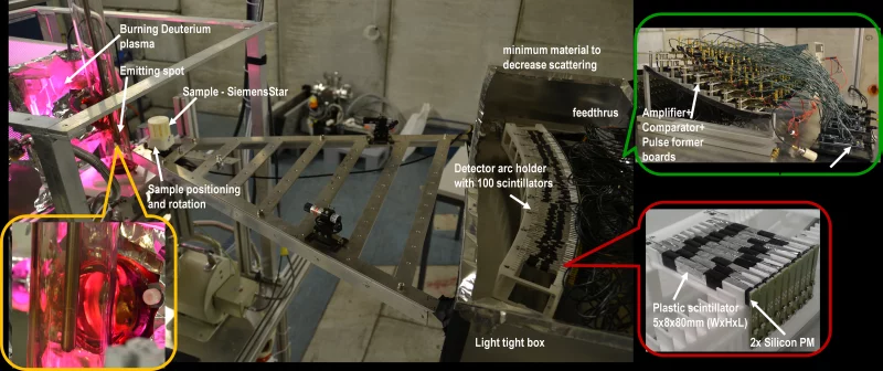
Neutron imaging, in general, is a useful, non-intrusive technique for visualizing low-Z materials (such as water or plastics) obscured by high-Z materials. When significant amounts of both low-Z and high-Z materials are present and extended samples have to be examined (such as in a full fuel bundle model), cold and thermal neutrons rapidly reach their applicability limit as the samples become opaque. In such cases one can benefit from the high penetrating power of fast neutrons. Besides extensively using the cold-neutron imaging technique, we also develop a fast neutron imaging system as a promising tool for nuclear fuel bundle investigations. The fast neutron imaging system consists of a D-D-fusion generator producing 2.5 MeV neutrons. It is complemented with a plastic scintillator detector arc enabling the tomography of the cross section of objects up to 15-20cm in diameter at a spatial resolution of about 2mm. The plastic scintillators are read out by silicon photomultipliers. This portable-sized system has a promising potential beyond nuclear thermalhydraulics.
SUBFLOW
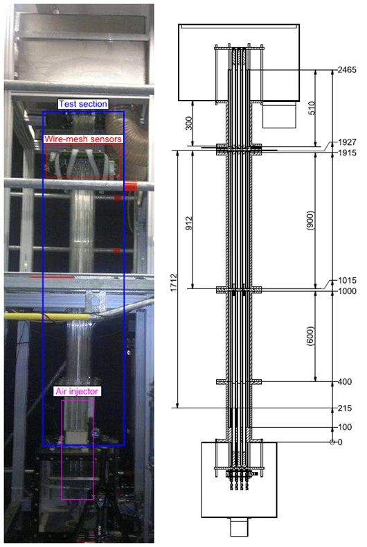
The motivation for the SUB-channel FLOW test facility (SUBFLOW) was to increase the knowledge of the complex flow phenomena inside a fuel rod bundle. The facility is an adiabatic test loop with an up-scaled (1:2.6) fuel rod bundle model, that has a 4×4 geometry. For visual observation purposes, all channel walls were made of the same transparent material, and half pipes were attached to the side walls. The modular design makes it relatively simple to modify the test section, for example to add or remove models of fuel rod spacers. For two-phase flow experiments, a special air injection system was developed in order to inject the same amount of air and bubbles of similar size in all of the 16 sub-channels. For the very first time, the wire-mesh sensor measurement technique was implemented in a rod bundle as two 64×64 conductivity wire-mesh sensors were installed in the upper part of the test section. The measurement technique enables one to study single- and two-phase flow behaviour with high spatial (about 2 mm) and temporal resolution (1250 Hz). The fact that the test section is designed for a pair of wire-mesh sensors, which are mounted at an axial distance of 15 mm, makes it possible to retrieve information about the velocity field by cross-correlating the data from the sensors.
FLORIS
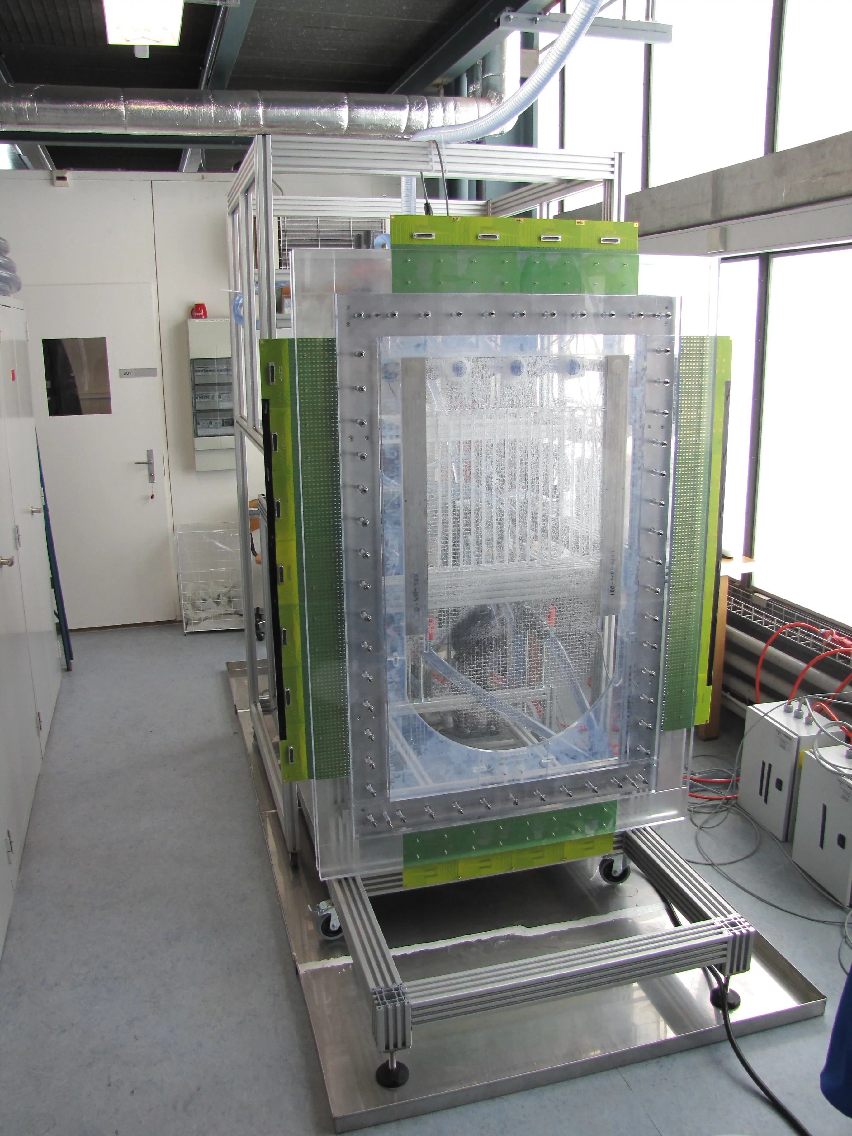
The experimental facility was designed and constructed with the main aim of studying density driven flow phenomena in the lower plenum of a BWR. FLORIS features a scaled-down, simplified, two dimensional vertical section of a reactor pressure vessel (RPV), made of transparent Plexiglas. The section is about 20 mm thick and comprises the downcomer, the lower and upper plena and the core region, built on a 1:10 scale. The four regions are shaped such as to take into account the presence of jet pumps and fuel assemblies. The section has two perpendicular inlet pipes in the downcomer region and three perpendicular outlet pipes in the upper plenum. All the openings are connected to two recirculation loops through different sets of valves, in order to allow a high degree of flexibility in the configurations that can be used during the experiments. The entire internal surface of the two-dimensional section is equipped with a wire-mesh sensor, featuring 112 transmitter wires and 64 receiver wires (1120 mm x 640 mm) . This allows one to effectively measure the tracer concentration over the entire flow domain of the vessel, except at the height of the inlet and outlet sections. The wire-mesh sensor implemented allows a high spatial- and time-resolved measurement (about 10 mm spatial resolution and up to 1250 Hz sampling rate, respectively, for the whole vessel) of the local concentration of the tracer injected into the system, spreading into the lower plenum and consequently entering the core channels.
GEMIX
Turbulent and laminar plane wake flows and their mixing characteristics have been a subject of research for more than a century and they are of fundamental relevance for many engineering applications, such as for the design of air foils, submarine and surface vessels, chemical and nuclear reactors as well as combustion chambers. A wake is either generated when a body is moved through a fluid leaving a region of velocity surplus or when fluid flows over a body leaving a region of velocity deficit behind it. Wakes as well as mixing layers grow with downstream distance, but there is still no consensus on the dominating mixing mechanism; some mechanisms proposed in the literature include engulfment, generation of waves and their breaking, eddy impingement and the radiation of turbulence from the high turbulence side through the interface to the low turbulence side. The experiments in GEMIX focus on the mixing in the wake generated downstream of a splitter plate separating initially two water streams having identical or different densities and identical velocities. In contrast to some wind tunnel experiments with low free stream turbulence levels, a certain amount of free stream turbulence ( 4 %) was explicitly desired and generated through screens since a higher turbulence level would be also the case for many engineering applications. Besides the velocity field measured with Particle Image Velocimetry (PIV) for the unstratified and weakly stratified case, some emphasis has been put on the developing concentration field in streamwise and transverse planes using two measurement techniques based on different measurement principles: Laser Induced Fluorescence (LIF) and wire mesh sensors (WMS) which allows for an interesting comparison of both techniques.
T-Junction
Mixing of coolant flows with different properties, e.g. temperature, is of significant interest for nuclear safety. A prominent example is mixing in piping T-junctions, where hot and cold streams join. It results in significant temperature fluctuations in the flow and near the piping wall. The induced wall temperature fluctuation can cause cyclical thermal stresses and subsequently fatigue cracking of the wall material. This has become an important issue in plant lifetime management of the ever-aging nuclear infrastructure. In this test section basic mixing studies have been performed in a T-junction geometry using wire-mesh sensors just down stream of the T enabling a time-resolved obseravtion of the mixing processes. The results have been used to qualify and compare with computational fluid dynamics approaches and models like U-RANS, SAS and LES.