

Supercritical fluids are of growing importance as reaction media in various fields of science and technology, including geochemistry, catalysis, surface chemistry and pharmaceutical chemistry. Prime examples are the crystal growth of minerals in supercritical water (SCW), the hydrothermal conversion of biomass to produce “green fuels”or the synthesis of fine chemicals and pharmaceuticals in supercritical fluids. As the chemistry involved can be fundamentally different compared to reactions under more conventional conditions (liquid, subcritical solvents or gases), it is indispensable to investigate these processes under in-situ reaction conditions. X-ray absorption spectroscopy (XAS) is a potent technique for obtaining local geometric (up to 6 Å) and electronic structural information about the X-ray absorbing atoms. On the other hand, X-ray diffraction (XRD) provides information about crystalline phases (long range order) and lattice parameters of solid samples. Owing to the large penetration depth of (high energy) X-ray radiation, XAS and XRD can be applied in-situ in the presence of gaseous or liquid reactants and solvents, using X-ray transparent cells or windows that are able to withstand the high temperatures and pressures necessary to reach supercritical conditions. Amongst the commonly used supercritical fluids (water, CO2and NH3), SCW presents the greatest challenge in terms of cell design, due to its critical parameters (pc = 22.1 MPa, Tc = 374°C) and its corrosive nature.
In particular, a cell that enables measuring XAS and XRD under typical SCW conditions needs to fulfill five main requirements:
- mechanical strength to withstand operating pressures of up to 30 MPa
- mechanical and thermal stability at temperatures up to 500°C
- resistance to corrosion under hydrothermal conditions
- absence of crystallinity that could cause additional diffraction of the X-rays
- sufficient X-ray transmittance at the desired photon energy.
In the field of catalysis it is furthermore desirable to investigate the catalyst during continuous operation whilst applying different reaction conditions such as flow rate, temperature, pressure or variation of reactants. For catalysis under supercritical conditions, this requires a continuous flow reactor that fulfills all of the above requirements. In addition, the reactor must allow for intimate contact of the supercritical fluid with the catalyst which is usually achieved by operating the reactor in a “fixed-bed” mode. In fixed bed mode, the catalyst is placed and secured as a closely packed bed of fine particles within the tubular reactor.
Setup & Methods
Design of the continuous flow, in-situ reactor
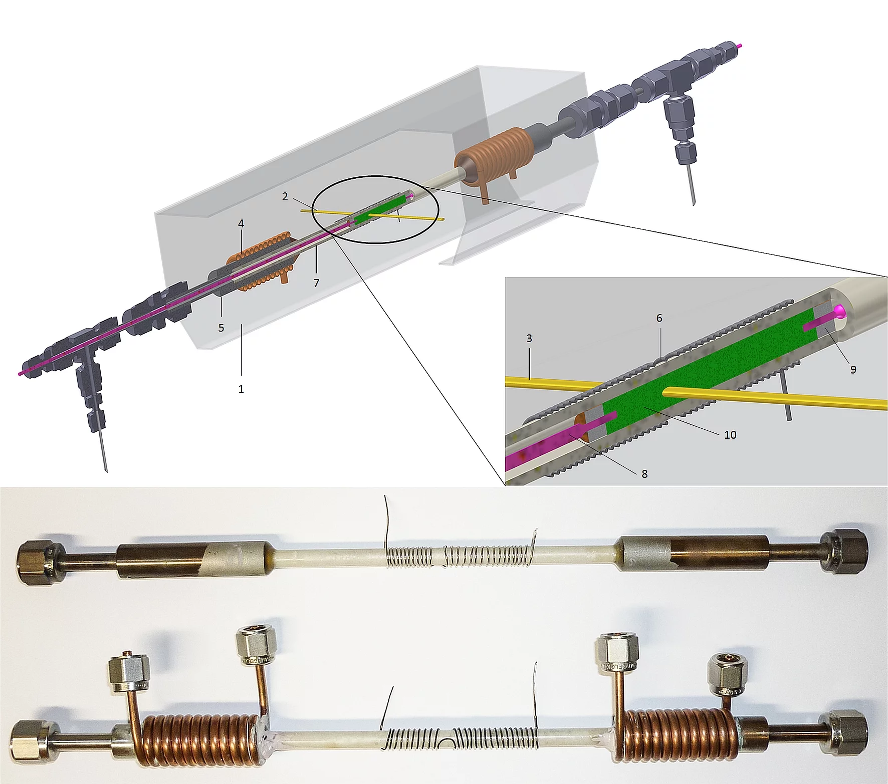
Figure 1 shows a 3D model of the complete reactor as well as an enlargement of the catalytic zone. As the centerpiece of the X-ray transparent cell, an aluminum nitride tube with dimensions was used. In order to integrate the AlN tube into a high pressure, liquid flow system, its ends were glued into stainless steel casings, using high performance epoxide glue. The ends of the steel casings were machined to 6 mm in diameter to allow for connection to Swagelok® fittings.
Due to the high heat conductivity of AlN and the relatively short reactor tube, the steel casings need to be water cooled in order to guarantee the mechanical stability of the epoxide glue and to prevent overheating. This was achieved by coils of copper tubing, wrapped around the steel casings. A flexible heating was realized with a coil of resistive wire, tightly wrapped around the center of the reactor. In order to allow the X-ray beam to pass through the heating unhindered, the twines in the center of the heating coil were pulled apart to a sufficient extent. A remotely controllable AC/DC converter was used to power the heating. For operation at the SuperXAS beamline at the Swiss Light Source, the in-situ reactor was supported on an aluminum rack and encased in a safety shield made from 3 mm aluminum sheets. Small openings in the safety shield at the level of the reactor tube allow the X-ray beam to pass through unhindered.
High pressure liquid feed system
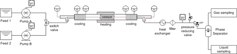
Figure 2 shows a scematic of the high pressure liquid feed system. The entire piping was constructed from stainless steel capillaries with Swagelok® connections. Capillary diameters were kept as small as possible to minimize the inner volume of the setup, improving the precision of liquid effluent analysis by eliminating dead space inside the piping.
The key components of the continuous flow setup are two syringe pumps that allow pumping liquids and viscous slurries with a flow rate precision of 5 µl/min at pressures up to 60 MPa. The two pumps are linked to the feed capillary by a six-port HPLC switch valve allowing for remote switching between different feeds. The switch valve is connected directly to the reactor, after which the effluent passes through a heat exchanger and a particle filter. The final component of the high pressure setup is a high precision back pressure regulator, optimized for low flow rates, where the effluent stream is allowed to expand directly from system to ambient pressure. Gaseous reaction products are then segregated from the liquid phase in a phase separator. Here, liquid samples can be taken for further analysis. The gas phase passes through a bed of calcium chloride to remove moisture and is analyzed online via a mass spectrometer or gas chromatograph.
Selected Results
Project Contact
In-situ characterization of catalysts under HP/HT conditions
Prof. Dr. F. Vogel
+41 56 310 2135
frederic.vogel at psi.ch