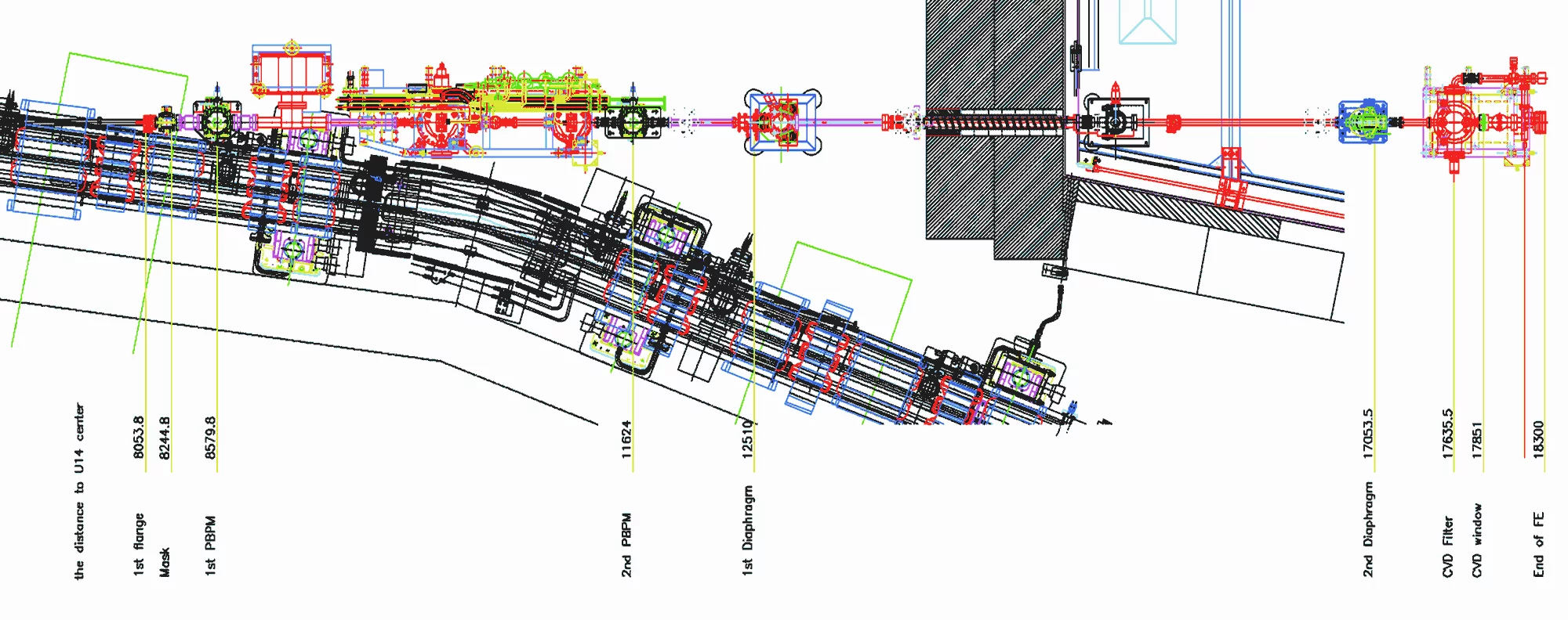
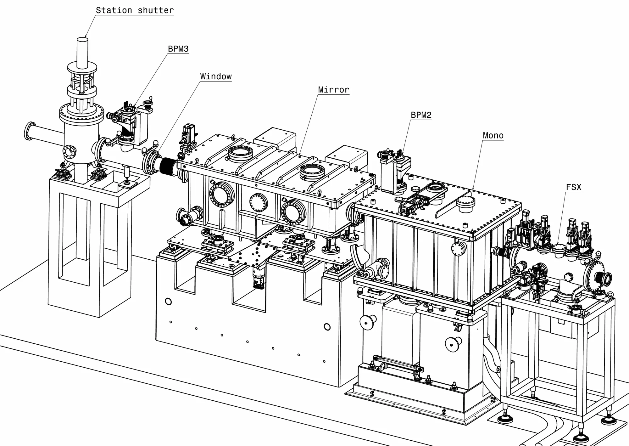
Optical elements
A document describing the optics geometry for the new setup for undulator radiation is described here
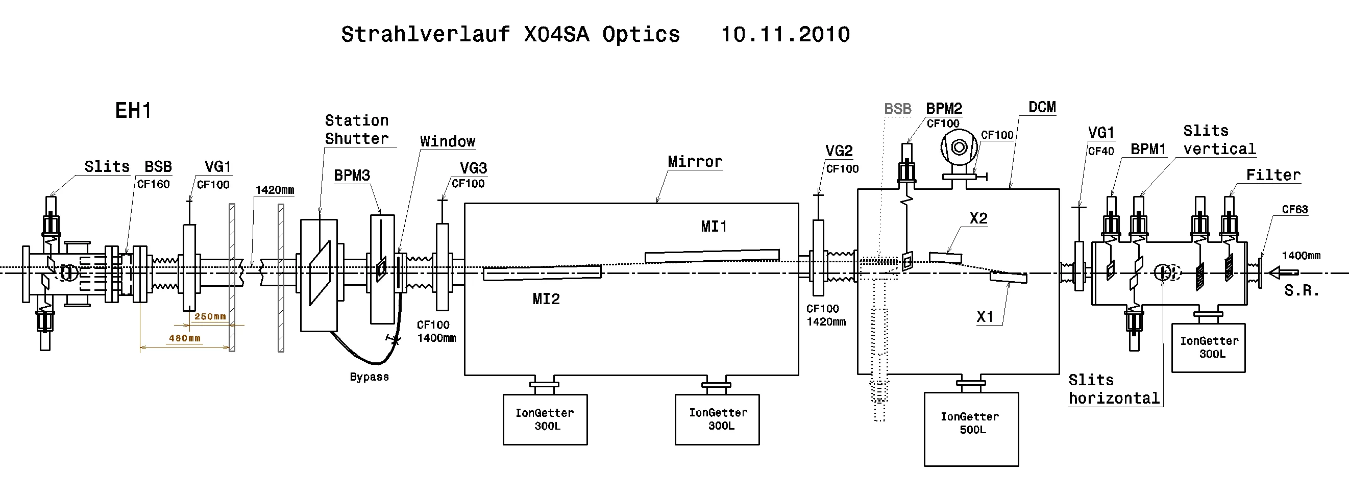
The optical elements of the beamline and their functions are listed here.
| Element | Function | Distance from source [m] |
|---|---|---|
| Filter | Beam attenuation | 18.8 |
| Optics slits | Beam definition | 19.2 |
| XBPM1 | Beam position monitoring | 19.4 |
| First LN2 cooled DCM crystal | Monochromatization | 20.142 |
| Second DCM crystal | Horizontal focussing | 20.2-20.5 |
| XBPM2 | Beam position monitoring | 20.69 |
| Mirror 1 | Vertical collimation | 21.514 |
| Mirror 2 | Vertical focussing | 22.214 |
| XBPM3 | Beam position monitoring | 23.3 |
| Station shutter | Extinction of experimental beam | 23.772 |
| Bremsstrahlung blocker | Blocking of direct beam and BS | 30.485 |
| EH1 slits | Beam definition | 30.9 |
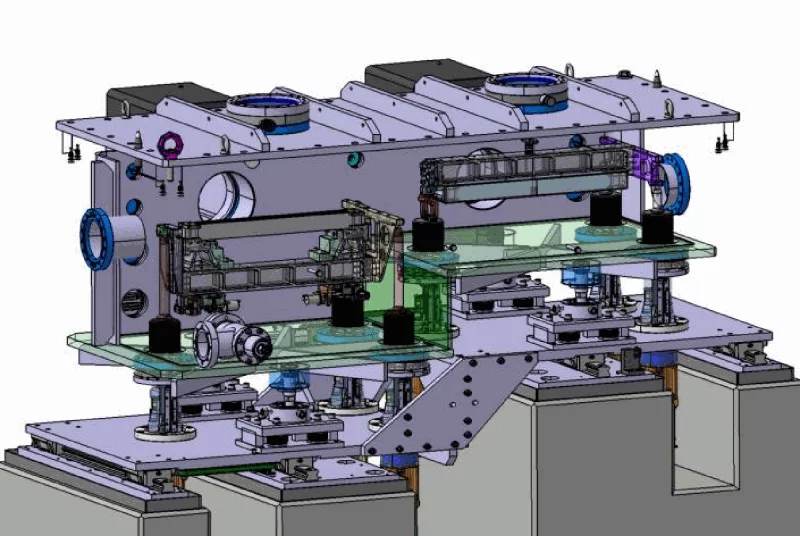
Double-crystal monochromator
The double crystal monochromator (DCM) consists of two Si 111 crystals which are precisely positioned and oriented in the X-ray beam.
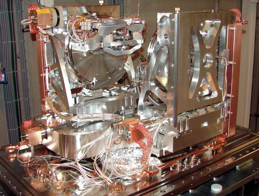
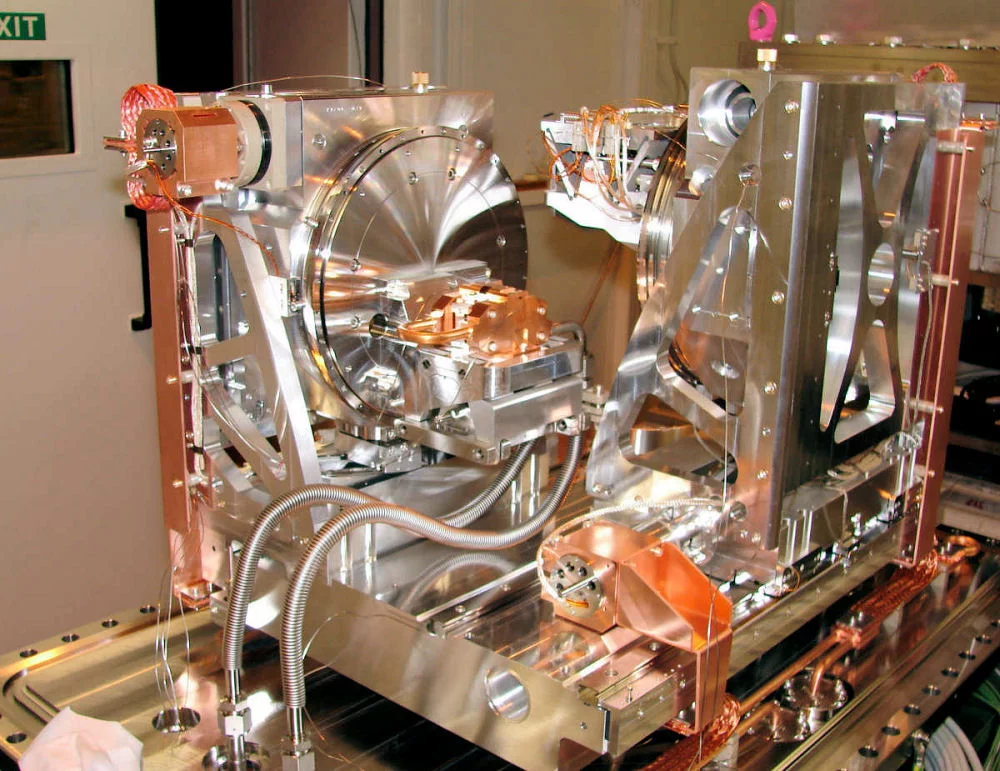
Two successive Bragg reflections, with an inherent energy resolution of 0.014 %, direct photons of the desired energy parallel to the incoming beam direction, but offset downward (out of the direct Bremsstrahlung beam) by 15 mm. Changes in photon energy require changes in the mirror angle and hence in the height of the DCM.
The polychromatic incoming beam (shown here as white) is monochromated by the first Si-crystal. The second Si-crystal is nominally set at the same angle and can be moved along a translation stage such that the outgoing beam (here, blue) is 15 mm lower in height than the incoming beam.
_An aperture 90 cm downstream allows the monochromated beam to pass, but blocks any high-energy Bremsstrahlung transmitted at the original height of 1400 mm. The large heat load absorbed by the first DCM crystal (up to 1 kW) causes it to deform, and a mechanical bending apparatus, ("TORII", developed at Hasylab), dynamically corrects this curvature._ The second crystal provides sagittal focusing; it is a ribbed crystal, cylindrically bent to a variable curvature radius (Rmin=1 m) in a flexure-hinge fixture developed at the ESRF.
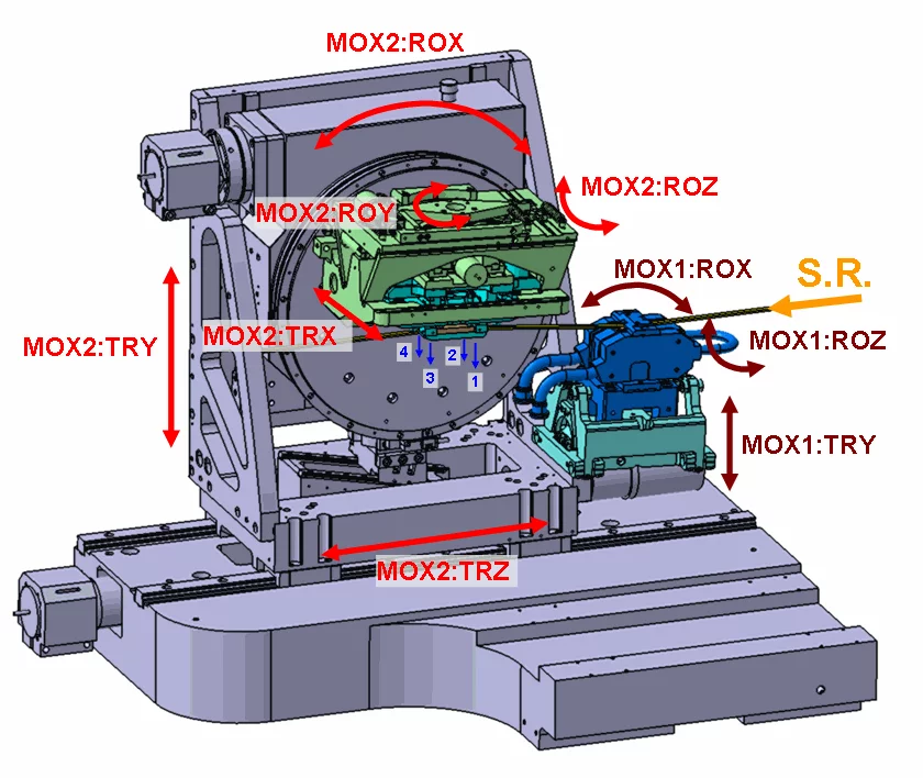
The DCM motors are controlled by EPICS channel widgets. A schematic of the motor movements and a table listing their functions are shown here.
The outgoing beam is shifted up by 20 mm compared to the incoming beam. See Table below for the motor functions.
| EPICS channel | Description |
|---|---|
| First crystal | |
| MOX1:ROX | rotation (pitch) of the first crystal stages around X axis |
| MOX1:ROY | rotation (roll) of the first crystal stages around Y axis |
| MOX1:TRY | translation of 1st crystal stage |
| Second crystal | |
| MOX2:ROX | fine adjustment of Bragg angle of 2nd crystal |
| MOX2:ROY | roll of 2nd crystal |
| MOX2:ROZ | yaw of 2nd crystal |
| MOX2:TRX | yaw of second crystal around its normal |
| MOX2:TRY | vertical movement |
| MOX2:TRZ | horizontal translation of 2nd crystal |
| MOX2:TRYA...D | flexing of 2nd crystal to produce sagittal (horizontal) focussing |
Mirrors
The beamline optics are shown below. The first mirror (MI1) provides vertical collimation and removes high-order harmonics. The mirror consists of a 1 m long Si blank, Rh-coated (K-edge: 23 keV), which can be tilted up to 5 mrad and bent (5 < R < 30 km) as required for the desired photon energy. The surface of the mirror has been polished to a rms roughness less than 0.5 nm and to a rms residual slope error less than 2.5 m rad.
The second mirror (MI2) is similar to MI1. A variable curvature permits vertical focusing at the experimental station in use. Since this focusing introduces a vertical divergence, which is undesirable, for example, in high-resolution powder diffraction, the user may choose to either set the radius of curvature to infinity or to remove MI2 from the beam altogether, the latter option causing an inclined beam.
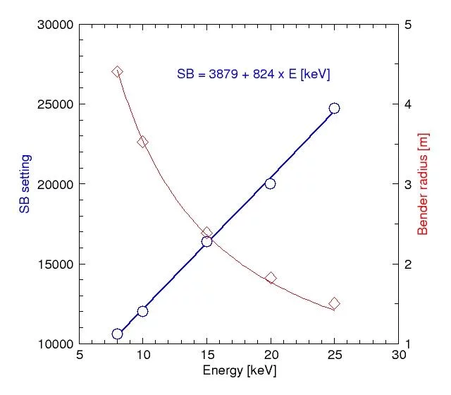
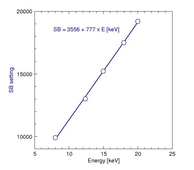
Horizontal (sagittal) focussing
Below are graphs and formulae for the optimal seetings for horizontal (sagittal) focussing of the second DCM crystal for different energies at the powder and surface diffraction stations.