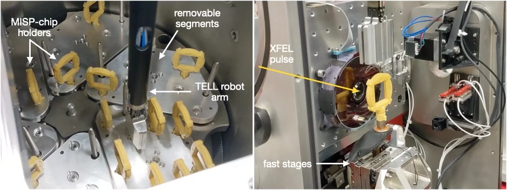
Fixed-target SFX at Cristallina
The fixed-targets that SwissMX typically support are: the PSI MISP (MIcro-Structured Polymer) chip (Carrillo et al., 2023) and the Max Plank Institut (MPI) SOS (Sheet-On-Sheet) chip (Doak et al., 2018), although other targets such as the Oxford (Horrell et al., 2021) and HARE chips (Mehrabi et al., 2020) could also be used. The TELL sample changer can be used to remotely store (at 80 % relative humidity) and exchange the MISP chip during a beamtime to increase beamtime efficiency.
Fixed-target data-collection
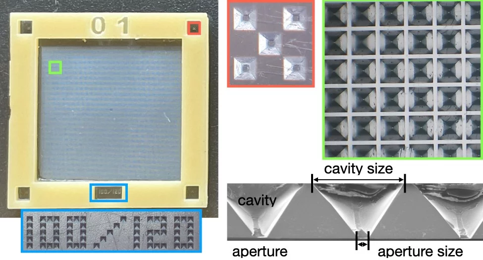
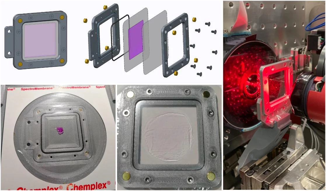
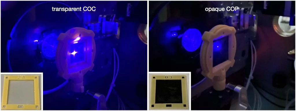
The PSI MISP chips
| transparent | opaque | ||
| material | COC | COP | |
| measurement type | SFX | SFX pump-probe | |
| fiducial width (µm) | 12.5 | 23.0 | 23.0 |
| pitch (µm) | 120.0 | ||
| cavity size (µm) | 100.0 | ||
| mean aperture size (µm) | 6.3 ± 1.0* | 8 ± 3.0† | |
| minimum crystal size (µm) | > 5.0 | > 10.0 | |
(*) Lysozyme crystals with a longest dimension as small as 4 µm have been caught in the chip apertures.
(†) It is very challenging to load single crystals into single wells as the crystal size decreases. An ideal crystal size for pump-probe in these chips is currently approximately 15-30 µm. Outside of these limits, the likelihood of crystal pump excitation decreases as either the number of crystals in the cavity increases or the crystal size limits the excited fraction. This is not to say it is impossible, but certainly not ideal.
MPI SOS fixed-targets
Pump-probe measurements
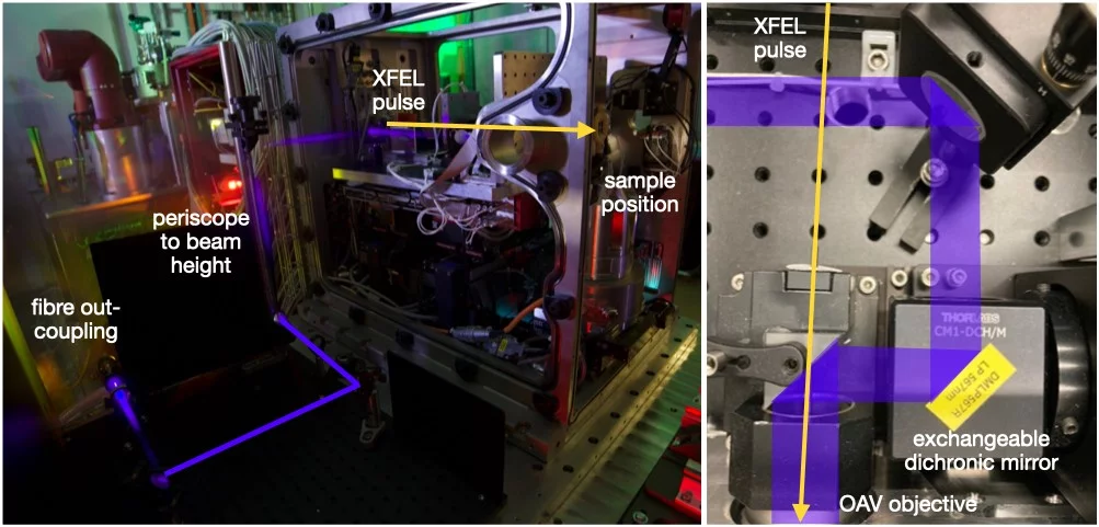
Laser coupling
Fixed-targets available for pump-probe
Available time delays
Two stage-motion routines are now available (July 2024): continuous and stop-go and these can be used effect different pump-probe delays. In continuous motion, as the name suggests, the stages do not stop at each aperture, but time their arrival precisely with the XFEL pulse. This means that data-collection rates can be maintained at 100 Hz, but are only applicable for time-delays < 1 ms. If you need longer delays, then you need to use stop-go where the stages move to an aperture and stop for a given number of pulses. This routine enables delays of > 1 ms, however, it will become very beamtime inefficient beyond 40-50 ms as the effective data rate drops proportionally with the delay, e.g., a 40 ms delay (+ 10 ms move) drops the data-collection rate to 20 Hz.
The implementation of hit-and-return type routines (Schulz et al., 2018) is a priority for the end of 2024 and we hope to have these commissioned for 2025.
| pulse-width (FWHM) | 3.2 ns (FWHM) at 450 nm |
| maximum pulse energy | 2 µJ |
| commissioned wavelengths | 410 - 700 nm |
| laser profile | 30 x 30 µm2 at 450 nm |
| ΔT range | 50 ns - 40 ms |
| fixed-targets | opaque MISP-chips |