Ferritic steels are used as structural components in the current operating nuclear power plants and more advanced variants, such as oxide-dispersion strengthened steels, are foreseen for the next generation of fission as well as fusion reactors. A crucial point to assess is the degradation of the mechanical properties induced by neutron irradiation and to improve their radiation resistance. As a consequence, investigations on neutron irradiated materials are required to measure the irradiation hardening (increase of flow stress) and embrittlement (decrease of toughness). However, only few neutron irradiation facilities are available and irradiations are very costly. In addition, handling and testing radioactive standard specimens, which are relatively big, can be done only in a limited number of hot-laboratories equipped with the appropriate hot-cells and shielded testing devices. Thus, over the years, ion beam irradiations have been contemplated as surrogate to neutron ones. However, the penetration depth of heavy ions up to 100 MeV remains lower than 10 mm in steels while protons with that energy penetrate deeper in steel, up to 1 cm. Hence, to determine the change in material strength following ion irradiations, micro-mechanical testing sampling tiny amount of materials is inevitable. Nano- and micro-indentation experiments have long been used for this purpose where empirical relationships between hardness values and tensile properties have been established. However, evaluation the tensile properties of the bulk from nano-indentation tests that produce deformed volumes with a characteristic length of few tens of microns is not straightforward. So, a program of nano-indentations tests has been tailored to address the possibility of extracting reliable mechanical material properties from indentation tests, where the underlying physics of size effect and length scale associated with indentation is well understood and taken into account.
Among the characteristic lengths, there are those associated with the structure (grain size, dislocations density, point defects, small defects clusters, etc…), and those related to the size of the plastic zone, or to the size of the indent. Thus, we can classify the size effects into two categories: structural size effect and indentation size effect. In order to separate these two effects, a Fe-9Cr ferritic model-alloy with an equiaxed grain microstructure was produced. The grain size of the alloy was about 80 to 100 mm.
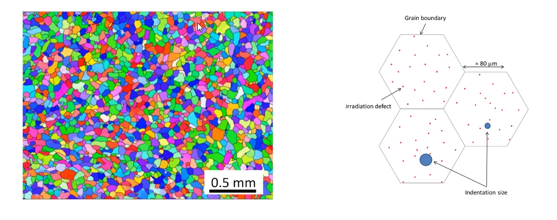
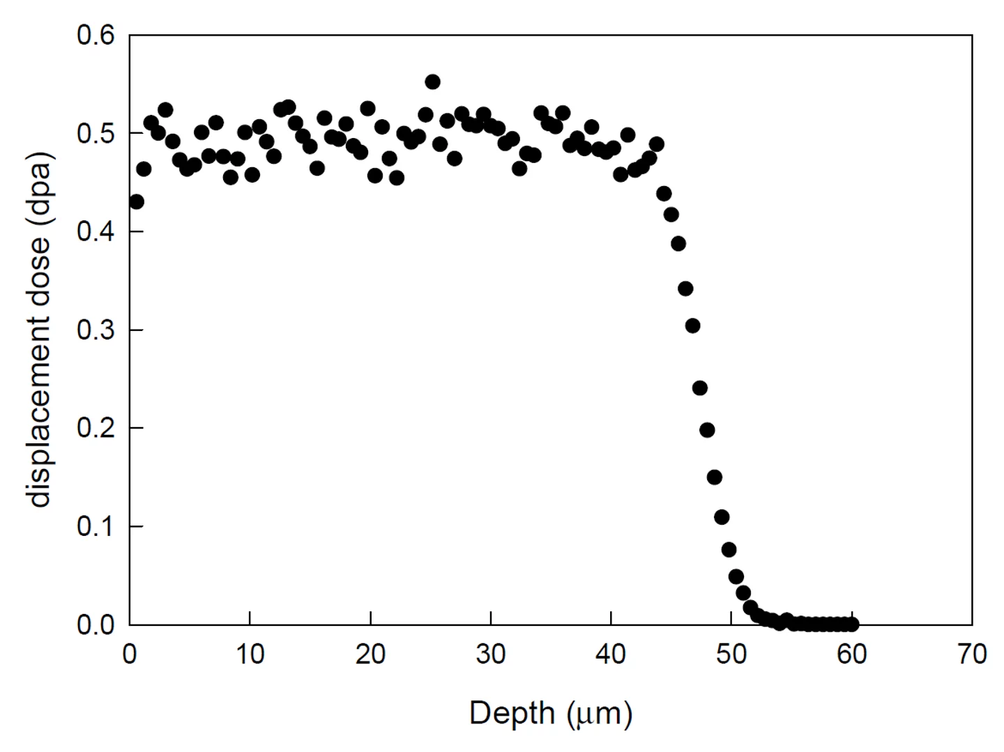
The choice of this microstructure was done to separate the effects of grain size from that of indentation size on spherical indentation stress obtained with different equivalent radii. In this work, a Berkovich tip was used for the indentation, from which an equivalent contact radius of a spherical indenter can be calculated. Figure 1 shows that, for the selected penetration depths, the equivalent contact radius of a spherical indent remains confined within one grain. In addition, another characteristic length scale was added, which was related to the density and size of irradiation defects introduced by irradiations with 7.2 MeV protons. The main advantage of such irradiations resides in the relatively large penetration depth of the protons into the specimens. As shown in Figure 2, a 50 mm thick layer can be homogenously irradiated; the homogeneity of the irradiation is realized with the use of a 24 aluminum foils degrader wheel. The plastic zone created by the nano-indentation remains within the irradiated layer so that a homogeneous irradiated volume of materials is sampled.
According to the dislocation slip distance theory, all possible obstacles limiting the mean free path of the moving dislocations have to be considered. The mean free path L of the moving dislocations can be calculated as the combined spatial frequency of all obstacles to dislocation motion, including the grain size, the dislocation density, and the size of the plastic zone itself represented by the indentation radius and regarded as an intrinsic obstacle. Thus, the measured indentation pressure Pm is given by:
1.
where Py is the spherical indentation stress of an infinite crystal that a dislocation would require to move in the absence of interaction with any obstacles, a represents the indentation size (contact radius), d is the mean grain size, ρs is the density of stored dislocations, k1–4 are constants, N is the density of irradiation-defects and d is the mean diameter of the defects. Since the indentation have been done in one grain the second term of the equation can be simply neglected, i.e. K2 = 0.
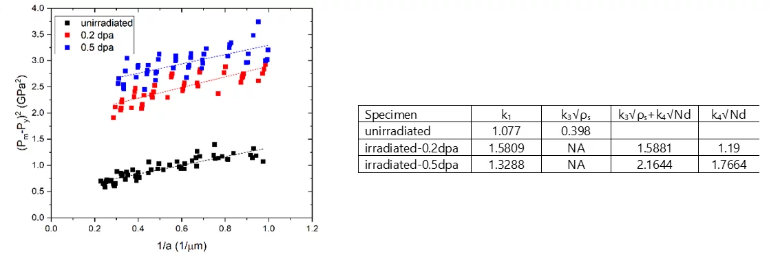
K1, K3 and K4 constants in Equation (1) were determined in the unirradiated condition as well as after two proton irradiation doses of 0.2 and 0.5 dpa (dpa=displacement per atom). Berkovich indentation were used for this purpose. For the unirradiated materials, we can plot (Pm-Py)2 against 1/a (see Equation (1) to generate a linear fit with a slope k1 and an intercept equal to .
2. for unirradiated material
For irradiated materials, an additional term has to be added to take into account the contribution of the irradiation hardening. In this case, the equation becomes:
3. for irradiated material
where k4 is a constant, N the density of irradiation-defects and d the mean diameter of the defects. For irradiated material, the intersect yields . A good estimate of Py for this material is 150 MPa. The (Pm - Py)2 data are plotted in Figure 3 and the values of the ki coefficients are reported in the adjacent Table. k1 value accounts for the ISE and is reasonably constant for the three datasets as expected.
represents the hardening contribution of the dislocation density is deduced from the unirradiated specimens and from
we can obtain the ratio of Nd between two irradiation conditions and consequently the relative evolution of the mean spacing between the irradiation defect clusters.
These results highlight the importance to properly separate the different contribution of the defects to the measured hardness of materials to isolate that of the irradiation hardening.
Contact
Pr. Dr. Philippe Spätig
Component Structural Integrity
Laboratory for Nuclear Materials
Paul Scherrer Institute
Telephone: +41 56 310 29 534, e-mail: philippe.spatig@psi.ch
Publications
- Song P., Spätig P., Effects of ball size and microstructures on indentation curves of Fe9Cr model alloys and tempered martensitic steel Eurofer97, (2022) Nuclear Materials and Energy, 30, 101143 – 101143. DOI: 10.1016/j.nme.2022.101143
- Song P., Yabuuchi K., Spätig P., Insights into hardening, plastically deformed zone and geometrically necessary dislocations of two ion-irradiated FeCrAl(Zr)-ODS ferritic steels: a combined experimental and simulation study, (2022), Acta Materialia, 234, 117991 – 117991. DOI: 10.1016/j.actamat.2022.117991


