The SLS-MS Powder Diffractometer is equipped with two independent detection systems: a multicrystal analyzer detector and a MYTHEN microstrip detector. Occasionally, a system of only 3 MYTHEN modules is mounted to either collect the diffracted signal also in the sagittal (horizontal) plane or to perform small-angle scattering by placing it very far away from the sample. We call it mini-MYTHEN II.
Multicrystal Analyzer
NOTE: DUE TO THE MUCH LONGER ACQUISITION TIMES AND CONSEQUENT HIGHER BEAMTIME USAGE, THE MULTICRYSTAL ANALYZER IS ONLY AVAILABLE TO USERS HAVING A PREVIOUS AGREEMENT WITH THE BEAMLINE SCIENTISTS, Dr. Antonio Cervellino and Dr. Nicola Casati. WITHOUT THAT, PROPOSALS BEAMTIME WILL BE CALCULATED FOR THE MICROSTRIP MYTHEN II DETECTOR.
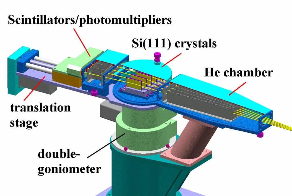
A crystal analyzer in the secondary beam greatly improves the overall angular (FWHM) resolution but at the expenses of the photon flux. A smart solution to recover some of the lost intensity was found by Hodeau et al. in 19981. Their idea consisted in placing several independent analyzer crystals at a fixed offset one with respect to the other and simultaneusly collecting the diffracted signal with one detector following each crystal.
The crystal analyzers are all mounted on a θ-2θ double goniometer as shown in Fig.1. The θ-axis goniometer plate positions the n-crystals (5 Si 111 crystals at our station) at the correct Bragg angle for every working photon energy, while the 2θ-axis goniometer plate positions, as a unit, the corresponding n-detectors (5 NaI(Tl) scintillators-photomultipliers at the SLS PD station) at the correct 2θ value for every working photon energy.
Mounting the crystals at an angular offset (nominal 2° at the SLS PD) allows one to satisfy the Bragg condition for the 5 (or more) crystals all together, by simply rotating the double goniometer in a 2:1 ratio. During the acquisition of the 2θ scan, the 5 analyzer/detectors intercept the diffracted peaks one after the other (4° earlier the 1st crystal, 2° earlier the 2nd crystal, at the calibrated 2θ angle the central crystal, 2° later the 4th crystal and 4° later the 5th crystal), yielding to independent 2θ scans. The counting statistics is, then, increased by a factor of n with the only requirement to merge the n signals after carefully correcting the offset.
Overall information on the multicrystal analyzer detector implemented at the SLS-MS PD station can be found in Gozzo et al, J.Alloys Compd, 2004..
A complete discussion on the modelling of the Overal Instrumental Resolution Function with the Crystal Analyzer detector can be found in Gozzo et al, JAC 2006.
MYTHEN II
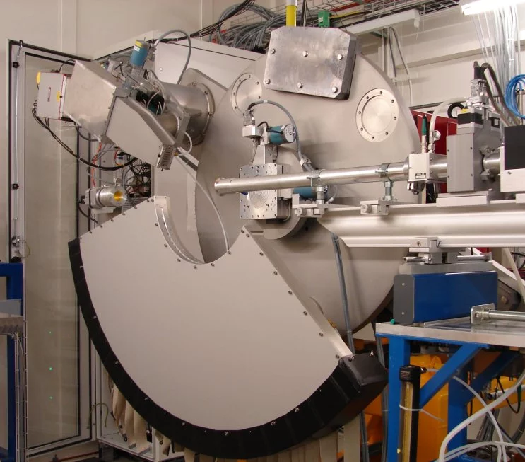
The powder diffractometer is equipped with the second generation MYTHEN II microstrip detector, constructed in house for time-resolved measurements and rapid acquisition of overview diffraction patterns.
This MYTHEN 1-D detector covers an angular range of 120° using 30'720 silicon elements, divided up into 24 modules of 1280 elements each (see Fig. 4). In contrast to spectra recorded using the analyzer detectors, the angular resolution is determined for all but the smallest samples by the size of that sample (typically a 0.2 mm capillary).
Although the microstrip detector is susceptible to air- and window-scattering near the sample, its approximately 1 keV energy resolution provides some degree of inelastic rejection. Each channel can count up to 3 MHz and has a dynamic range of 224 (16 Mcounts), with effectively zero dark noise. The entire angular range of the detector can be read out in a few milliseconds. The present maximum frame rate is 5 Hz, but it is planned that in the future a frame rate of 10 kHz will be possible.
The Instrumental Profile of MYTHEN detector in Debye Scherrer geometry has been recently performed and can be found in Gozzo et al, ZKrist, 2010.
mini-MYTHEN II
A smaller detector, comprising only 3 modules of the second generation MYTHEN II microstrip detector, is available at the beamline. It can be positioned wherever an experiment dictates the position of a second detector. This MYTHEN 1-D detector uses 3840 silicon elements, divided up into 3 modules of 1280 elements each. Performance and characteristics are as the MYTHEN II above, the anglular or transferred momentum range depend of course on the installation position. Any of the two MYTHEN detectors can be slaved to the other in order to acquire simutaneous and synchronous pattern also in time-resolved mode.
Pilatus 6M
This silicon-based large area detector is made of 60 modules of ~100k pixels, 172x172 microns each in size. There are small gaps in between modules, coverage of these small areas cannot be guaranteed although the detector is normally mounted on a motorized table that allows adjusting partially its vertical positions. It can be positioned above the beam path at a minimum distance of 400 mm and below the beam path (or central) at a minimum distance of 820 mm. Its sensitive area is 423.6 x 434.6 mm large. Its angular calibration has to be performed each time depending on the geometry. Flatfield corrections are presently not available, although this has a very limited impact on powder diffraction measurements werer typically hundreds of pixels are integrated for intensity. The angular resolution per pixel is, in standard geometries, worse than the one of the Mythen.
N. Casati, reviewed on September 5, 2016


