Goals
Photoelectron diffraction experiments benefit mainly from high photon flux and tunable photon energy. High photon flux is required to compensate for the low emitter density due to surface sensitivity. Tunable photon energy is needed for several reasons. The photoelectron cross-section varies strongly with photon energy. It is in general highest at low photon energy, while there are a few notable exceptions due to interference or resonant excitation. For structural analysis from angle- and energy-scanned photoelectron diffraction it is also important that the wavelength of the photoelectrons determines the diffraction conditions.
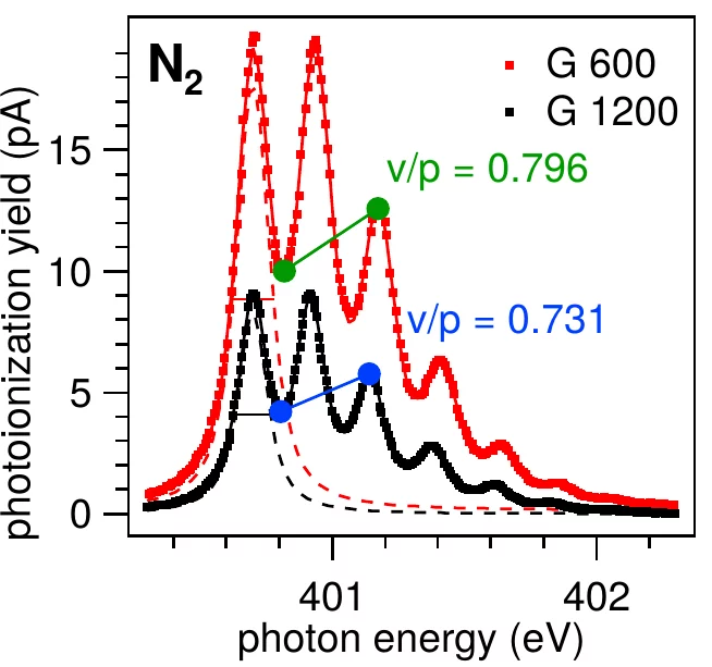
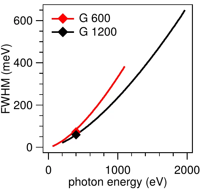
The PEARL optics is designed for the photon energy range 100-2000 eV, covering the core-level XPS lines of most chemical elements. The beamline should deliver high photon flux at photon energies between 500 and 1000 eV. For measurements with chemical state specificity, the energy resolution should be tunable to at least 0.1 eV in this energy range.
The PEARL optics is designed for the photon energy range 100-2000 eV, covering the core-level XPS lines of most chemical elements. The beamline should deliver high photon flux at photon energies between 500 and 1000 eV. For measurements with chemical state specificity, the energy resolution should be tunable to at least 0.1 eV in this energy range.
Concept
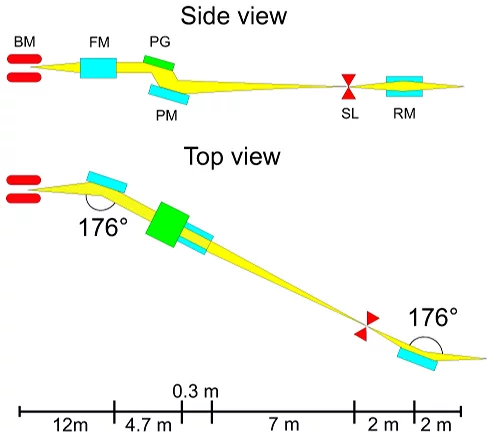
The X-ray optics are based on a plane-grating monochromator operating in non-collimated beam and negative diffraction order.
This design provides high photon flux and tunable photon energy in the range 100-2000 eV at an energy resolution E/ΔE up to 7000.
A switchable refocusing mirror allows to switch spot size and flux density on the sample. Fig. 1 shows a schematical diagram.
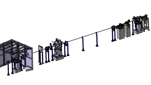
Fig. 2 shows a 3D rendering of the optics segment of the beamline. The X-rays from the synchrotron enter the beamline from the left hand side. The major components (on concrete supports) are, from left to right: Focusing mirror, monochromator, exit slit, gas cell (diagnostics), refocusing mirror. The beam exits on the right side to the experimental station (not shown).
Fig. 2 shows a 3D rendering of the optics segment of the beamline. The X-rays from the synchrotron enter the beamline from the left hand side. The major components (on concrete supports) are, from left to right: Focusing mirror, monochromator, exit slit, gas cell (diagnostics), refocusing mirror. The beam exits on the right side to the experimental station (not shown).
Performance
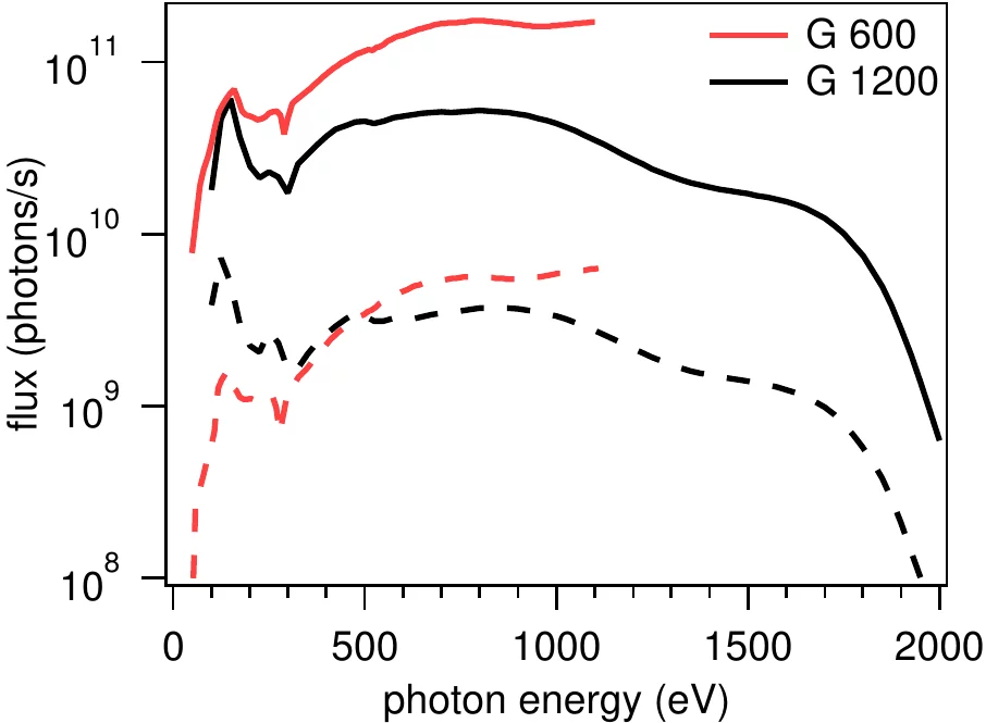
Fig. 3 shows the measured photon flux for the two installed monochromator gratings at two aperture settings for best resolution and for highest flux.
Exceeding the design goals, the beamline delivers smoothly tunable photons over the range from 60 to 2000 eV.
For details on beamline performance and calculations, cf. Refs. 1 and 2.
For details on beamline performance and calculations, cf. Refs. 1 and 2.
References
- P. Oberta, U. Flechsig, M. Muntwiler, C. Quitmann: Optical design study of the PEARL beamline at SLS, Nucl. Instr. and Meth. A 635, 116 (2011), DOI: 10.1016/j.nima.2011.01.076
- M. Muntwiler, J. Zhang, R. Stania, F. Matsui, P. Oberta, U. Flechsig, L. Patthey, C. Quitmann, T. Glatzel, R. Widmer, E. Meyer, T. A. Jung, P. Aebi, R. Fasel, T. Greber: Surface science at the PEARL beamline of the Swiss Light Source, J. Synchrotron Rad. 24, 354 (2017), DOI: 10.1107/S1600577516018646

