Please note that due to the complexity of sample alignment and the diversity of sample types and shapes, we are not able to provide customized sample holders to beamline users. Please discuss sample mounting options well in advance with the beamline staff. Technical drawings of the sample geometry are available for download from the Documents section below.
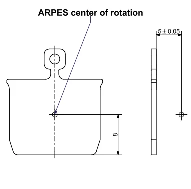
Fig. 1 shows the location of the center of rotation with respect to the sample plate. The sample must be mounted such that its surface lies 5.00 mm above the plate. This distance is given by the center of rotation of the manipulator in the ARPES chamber and the focal depth of the photoelectron spectrometer. For angle-scanned experiments in particular, the sample surface must be mounted to within 0.05 mm of the rotation center. For non-angle scanned measurements, the tolerances are relaxed.
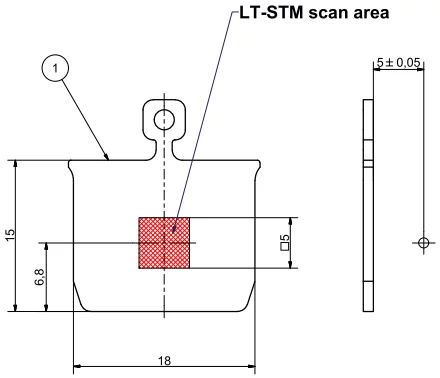
Fig. 2 shows the coarse scan range of the scanning probe microscope. Note that the measurement position in the ARPES chamber (given by the center of rotation) lies within the coarse scan range, but it is not centered. In the surface normal direction, the STM scanner can access the whole range from 0 to 5 mm above the sample plate.
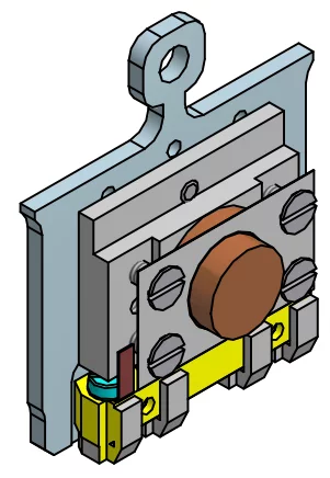
Fig. 3 shows a reference design for hat shape samples that has been used by the in-house group at PEARL for a series of single crystals. The sample is mounted on an spacer which is customized for a perfect alignment of the surface. The spacer and the base plate have additional bores for fastening and for line of sight between the ceramic heater of the preparation manipulator and the bottom of the sample. Two of the four-point probe contacts can be used to attach a type K thermocouple to the sample. If thermocouple readout is not used, the contact bank does not need to be installed. (Note that accurate temperature reading may require extra calibration.)
Frequently Asked Questions
Sample holders for angle-scanned photoemission are delicate devices and typically tailored to one specific sample or substrate. Due to the variety of sample shapes and requirements on the materials and machining we cannot provide customized sample holders. We can provide drawings of our standard sample holders for hat-shape crystals, wafers and cleaved crystals. If this requirement poses a problem to your project please get in contact with the beamline manager early.
Is there an exact thickness required of the sample plates?
The tolerances of the sample plates on the market are too wide for our manipulators. If they are too thick they will not fit in the manipulators. If they are slightly too thin, they will fit but might move in the receptacle while rotating the preparation manipulators. On the ARPES manipulator and in the STM, this problem is less critical.
Are the ears at the rear end of the sample plate required?
The ears define the insertion depth of the sample in the manipulators. They are not strictly required but positioning will be less reproducible without them. In the preparation manipulator, the plate may move, which may cause the sample to get scratched or shadowed from the evaporators.
What are the requirements of the handle?
We use Ferrovac wobblesticks with pincers that grab the sample plate by the head and neck of the handle. The hole is not necessary. The handle should not be bent as it might break off during handling.
Is there any issue with the sample being only 1 or 2 mm thick?
For efficient angle scans, the positioning of the surface to (5.00 +/- 0.05) mm is crucial. For experiments that don't require angle scans, the requirements can be relaxed. However, there is a gear box on the manipulator which blocks the beam at 25° grazing angle, while the beam normally comes in at 30°. For 3 mm and thinner samples the manipulator must be moved off-center to compensate.
How do you monitor temperature for annealing and cooling?
We have a calibration curve for heating on the preparation manipulator which we believe is accurate to 25 K on our samples. The curve was measured with a thermocouple attached on top of a dummy sample, and at the same time by a pyrometer. Usually, we monitor the temperature by a thermocouple attached to the manipulator and the pyrometer. If your project requires an accurate temperature reading please get in contact with the beamline staff early.
In the analysis chamber, the temperature range is 35-450 K, measured on the surface of a sample. There is a Si diode in the manipulator to measure temperature. At low temperature the difference between actual temperature and the diode is 15 K.
It is possible to attach a type K thermocouple to the sample on the plate and contact it via one contact pair of the Omicron 4-point probe contacts. It is, however, tricky to make and connect a reliable thermocouple.
Is it possible to transfer a cold sample?
The transfer system is at room temperature. However, we manage to transfer samples quickly enough so that they do not warm up to more than 200 K. We have checked this on one system which undergoes an irreversible transition at 220 K.


