

X-ray microscopy has potential in imaging thick samples with high resolution due to the large penetration depth and the short wavelength of x rays. As a challenge, the absorption contrast is low, especially when imaging biological samples with hard x rays. Zernike phase contrast microscopy can be used to image samples that only cause a phase shift to the incident light. The method is well established in visible light microscopy and has been used with x-rays for the past 20 years (G. Schmahl et al, Optik 97, 181 (1994)).
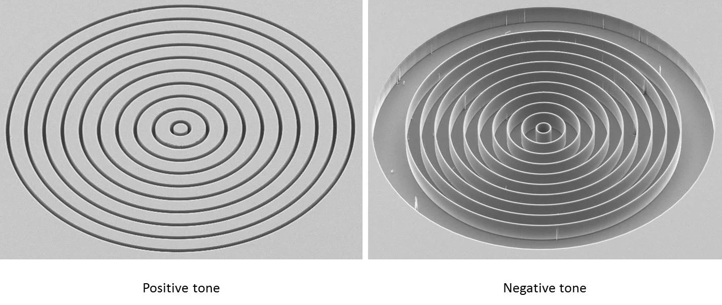
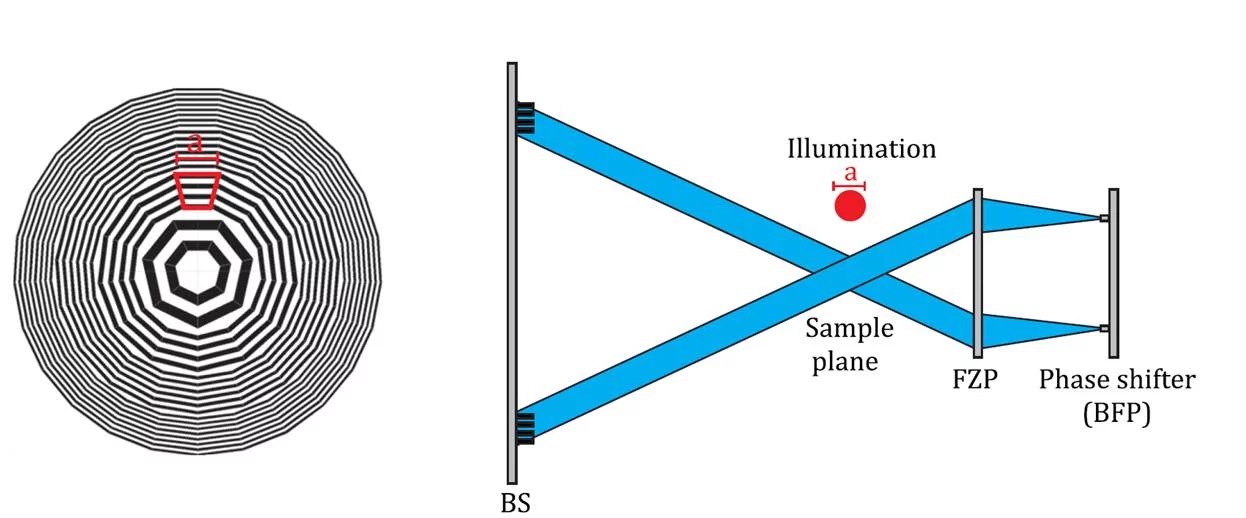
Providing suitable illumination of the sample is one of the key issues in Zernike x-ray microscopy. We have developed a new type of diffractive x-ray optical element which can be used as beam-shaping condenser lenses (see Fig. 1). These devices produce a flat-top illumination spot on the sample matched to the field of view. The design of the beam-shaping element is based on an ordinary Fresnel zone plate, which is divided into subfields. Each subfield consists of a linear grating with constant line orientation and period. The size of the illumination spot can easily be designed depending on the geometry and requirements of the specific experimental station. Each of the subfields of our beam shapers illuminates the sample from a well-defined direction, allowing us to manipulate the phase of the unscattered object wave using a phase shifting plate (see Fig. 2) in the back-focal plane of the objective lens.
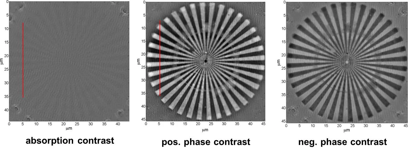
The technique was developed for photon energies spanning from hard x-rays [1] down to the tender x-ray range [2], in collaboration with the Tomcat beam line at SLS, beamline I13 at the Diamond Light Source, and beamline P05 of PETRA3 at DESY. Figure 3 shows x-ray images of a test object revealing the greatly enhanced contrast when using the Zernike method. We have also shown, how Zernike x-ray microscopy can be combined with high Resolution x-ray tomography [3], scanning x-ray microscopy [4], and ptychographic imaging [5].
Publications
- I. Vartiainen, R. Mokso, M. Stampanoni, and C. David, Halo suppression in full field X-ray Zernike phase contrast microscopy, Optics Letters 39 (2014) p. 1601
- I. Vartiainen, M. Warmer, D. Goeries, E. Herker, R. Reimer, C. David and A. Meents, X-ray Zernike phase contrast imaging of biological samples with tender X-rays at 50 nm Resolution, Journal of Synchrotron Radiation 21 (2014) p. 1
- M. Stampanoni, R. Mokso, F. Marone, J. Vila-Comamala, S. Gorelick, P. Trtik, K. Jefimovs, and C. David, Hard X-ray 3D phase-contrast nanoimaging, Physical Review B 81 (2010) p. 140105
- I. Vartiainen, C. Holzner, I. Mohacsi, P. Karvinen, A. Diaz, and C. David, Artifact characterization and reduction in scanning X-ray Zernike phase contrast microscopy, Optics Express 23 (2015) p. 13278
- I. Vartiainen, I. Mohacsi, K. Stachnik, M. Guizar-Sicairos, C. David, and A. Meents, Zernike X-ray Ptychography, Optics Letters 41 (2016) p. 721